Cam locking tool fabrication
#1
 01-24-2010, 04:25 PM


Join Date: Jul 2009
Location: Sebastian, FLA
Posts: 459
Likes: 0
Received 0 Likes
on
0 Posts
I'm posting this writeup at the request of a member friend. It's a quick and easy way to fabricate a cam locking/holding tool for head reassembly. Please pardon my dirty finger nails  .
.
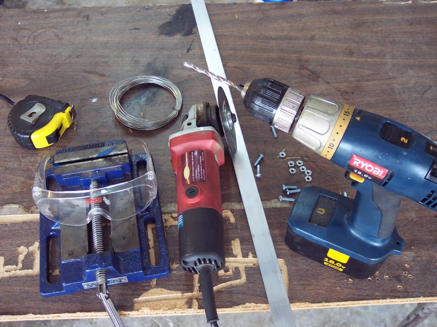
Here are most of the tools

John.. if you watching, the safety glasses are for you .
.
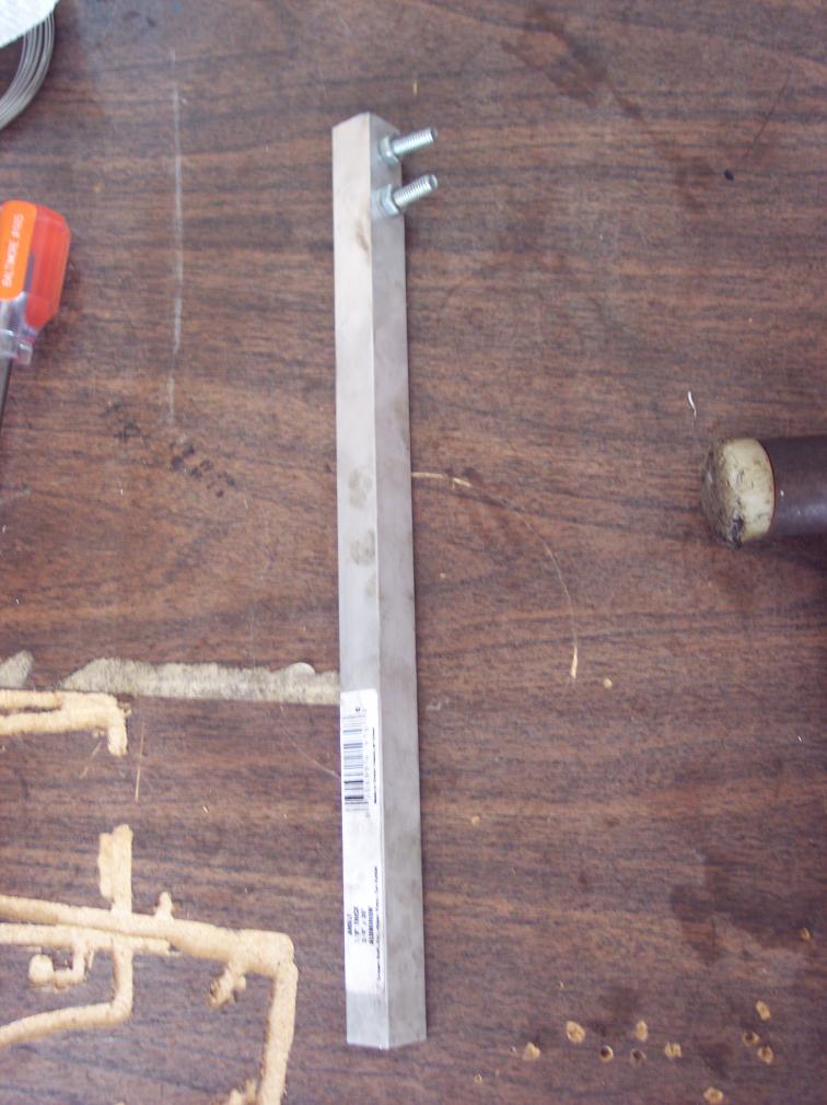
The aluminum is purchased at Home depot. 1" flat stock. I like aluminum over steel because it's easier to work with and softer in case it comes up against the seal housing.
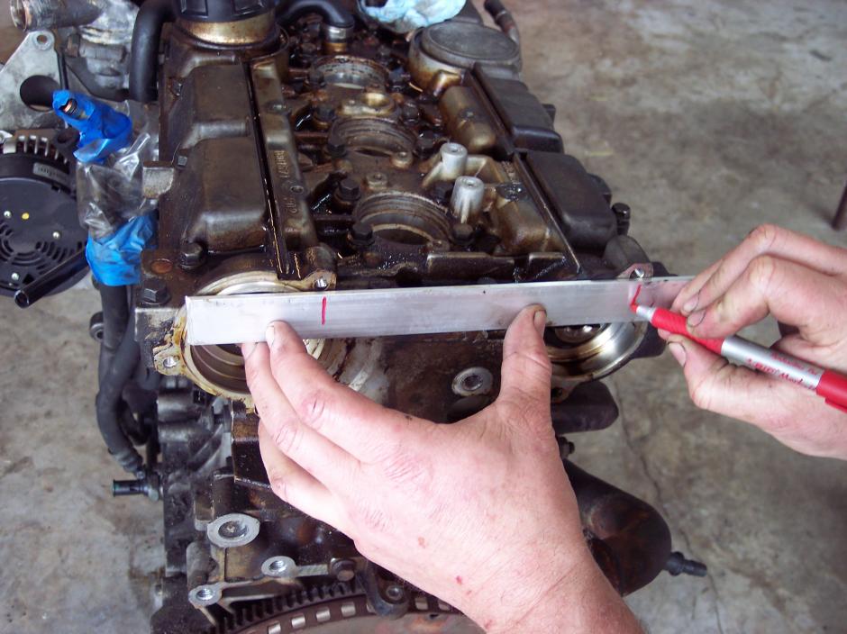
1. Measure and cut the horizontal support, about 10". Use care with the cutoff disk with aluminum it's not as easy as steel. you really have to hold on tight. Then transferr the hole locations for the distributor cap hole and the cam position sensor (CPS) as shown.
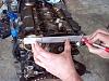
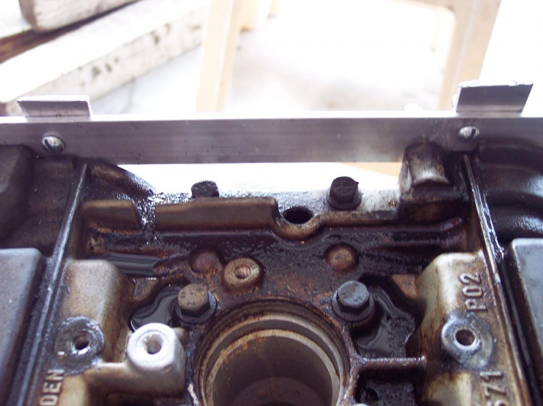
Drill the holes at close to the sizes of the CPS and dist. cap screws but favor the lower edge of the horizontal. Installed it should look something like this. Use the dist. cap screws but add over sized nuts to make up the difference as shown and us the CPS screw.
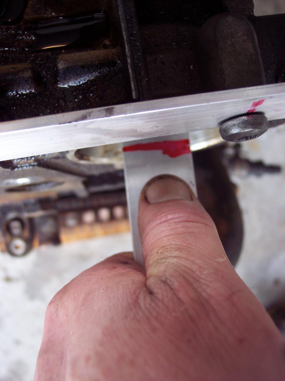
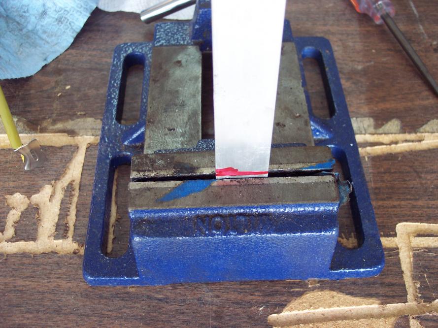
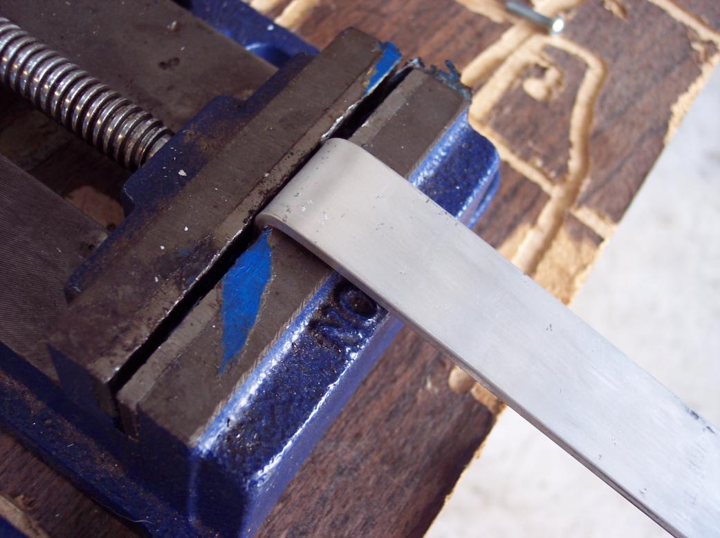
insert stock into the cam slot and mark at the edge of the horizontal. Then put it into a vise(brake if you're fortunate enough to have one) and bend the flat stock. The pic shows the stock positioned in the vise above the mark..Don't do this put it right at the mark and bend.
Insert into the slot, mark the verticals above the the horizontal and cut off above the horizontal support.
.Here are most of the tools
John.. if you watching, the safety glasses are for you
. The aluminum is purchased at Home depot. 1" flat stock. I like aluminum over steel because it's easier to work with and softer in case it comes up against the seal housing.
1. Measure and cut the horizontal support, about 10". Use care with the cutoff disk with aluminum it's not as easy as steel. you really have to hold on tight. Then transferr the hole locations for the distributor cap hole and the cam position sensor (CPS) as shown.

Drill the holes at close to the sizes of the CPS and dist. cap screws but favor the lower edge of the horizontal. Installed it should look something like this. Use the dist. cap screws but add over sized nuts to make up the difference as shown and us the CPS screw.

insert stock into the cam slot and mark at the edge of the horizontal. Then put it into a vise(brake if you're fortunate enough to have one) and bend the flat stock. The pic shows the stock positioned in the vise above the mark..Don't do this put it right at the mark and bend.
Insert into the slot, mark the verticals above the the horizontal and cut off above the horizontal support.
Last edited by Bobec; 01-24-2010 at 07:29 PM.
#2
01-24-2010, 05:07 PM
Join Date: Jul 2009
Location: Sebastian, FLA
Posts: 459
Likes: 0
Received 0 Likes
on
0 Posts
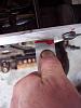
Hold the bent vertical in the cam slot, mark and cut. Then hold the cut piece in the cam slot and mark a hole location that will allow a screw to attach the horizontal to the vertical. Because the stock is only 1" attention needs to paid to the screw heads. see pic from back side.
Drill hole in the vertical and use it to mark a hole in the horizontal.
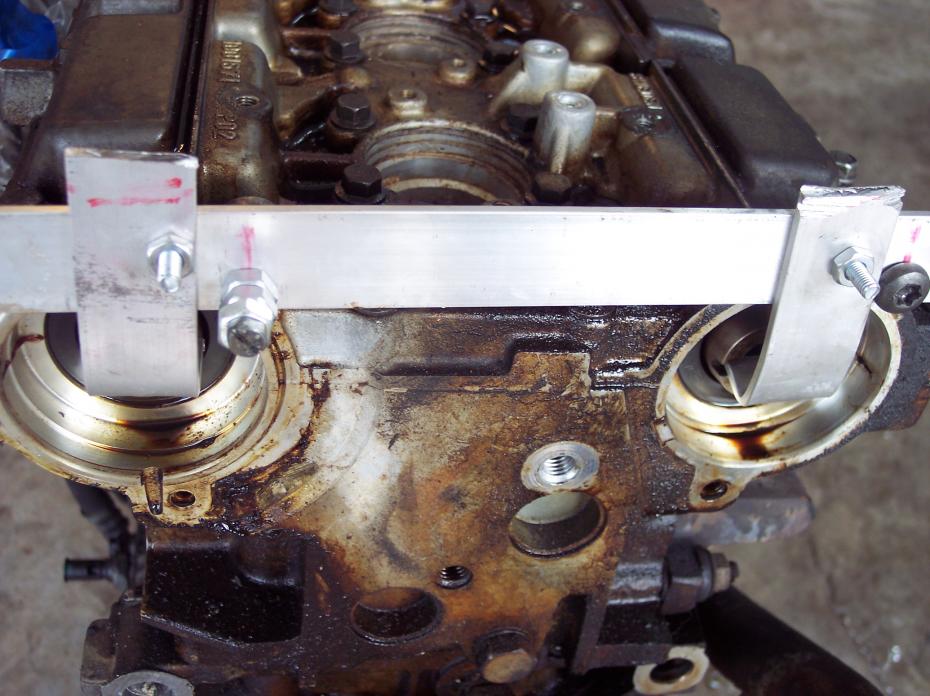
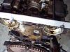
yes... this motor was beeding big(BIG) time from it's cam seals. I can't wait to measure the cylinders.
Bolt the verticals to the horizontal with 10-32 or 10-24 and tighten every thing up. Worked well for me... hope it helps.
Gabe, don't build one(unless you really want to) I'll send you the one I made for the write up. An early graduation gift, just PM your shipping address. Yeah I still need those parts so I'll PM you.
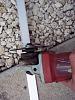
PS... I almost forgot. another simple tool I made to remove the aux./serpintine belt. 10-24 screws in aluminum angle bought at Home Depot. Use washers though and tighten the screws well.
Bobec
Last edited by Bobec; 01-24-2010 at 06:12 PM.
#3
01-24-2010, 06:13 PM

#4
02-07-2010, 01:30 PM


#7
07-18-2010, 12:44 AM

Thank you so much for this writeup, could someone answer a few questions for me about it though?
I have a 94 850 turbo with no markings on the cams, during my mechanics repair of the head gasket, after removing the cams, the crank spun, and with no marks on the crank, they were stumped how to get it timed, they have given up, and I am going to attempt to time it back, will this tool allow it to be timed incorectly? Or if I use it, it will always be in time? I just am a bit confused, if someone could please explain what they would do to get my car back in time?
I have a 94 850 turbo with no markings on the cams, during my mechanics repair of the head gasket, after removing the cams, the crank spun, and with no marks on the crank, they were stumped how to get it timed, they have given up, and I am going to attempt to time it back, will this tool allow it to be timed incorectly? Or if I use it, it will always be in time? I just am a bit confused, if someone could please explain what they would do to get my car back in time?
#8
08-14-2010, 01:12 AM

Junior Member
Join Date: Aug 2010
Location: Florida
Posts: 1
Likes: 0
Received 0 Likes
on
0 Posts
I must say this is a great forum I have ever visited. I love to read topic that are informative and actually have good content. Thank you for sharing your experiences and I look forward to reading more.I also like the perspective you brought to this subject. Its like you have an insight that most people haven't seen before. Keep it up


#12
10-06-2011, 06:58 AM

Junior Member
Join Date: Sep 2011
Location: CT
Posts: 1
Likes: 0
Received 0 Likes
on
0 Posts
#13
05-02-2012, 11:08 PM

Attachment 2089
Attachment 2090
Hold the bent vertical in the cam slot, mark and cut. Then hold the cut piece in the cam slot and mark a hole location that will allow a screw to attach the horizontal to the vertical. Because the stock is only 1" attention needs to paid to the screw heads. see pic from back side.
Attachment 2091
Drill hole in the vertical and use it to mark a hole in the horizontal.
Attachment 2092
yes... this motor was beeding big(BIG) time from it's cam seals. I can't wait to measure the cylinders.
Bolt the verticals to the horizontal with 10-32 or 10-24 and tighten every thing up. Worked well for me... hope it helps.
Gabe, don't build one(unless you really want to) I'll send you the one I made for the write up. An early graduation gift, just PM your shipping address. Yeah I still need those parts so I'll PM you.
PS... I almost forgot. another simple tool I made to remove the aux./serpintine belt. 10-24 screws in aluminum angle bought at Home Depot. Use washers though and tighten the screws well.
Attachment 2093
Bobec
#14
05-03-2012, 10:10 PM

#15
10-09-2012, 03:32 AM

Junior Member
Join Date: Jun 2012
Location: Dhaka, Bangladesh
Posts: 3
Likes: 0
Received 0 Likes
on
0 Posts
Once you hold your daily bent directory under the cam slot, picture and also cut. Then handle your reduced component in the cam slot as well as grade an pit location that will let an **** to be able to attach your daily side to side for the straight. Because the stock is merely 1" interest have to hired to the **** ventures. meet pic on side aspect.

#17
11-22-2012, 01:14 AM

Junior Member
#18
03-18-2013, 01:55 AM

#19
03-30-2013, 04:47 PM

question ; how do we know if the cams being level how do i know if they are not 180 degrees off...gears were off cams...Okay...I put them on the bench and it seems there is only one way that the timing marks will be lined up and slots on cams level
Last edited by Mike Sharpe; 03-30-2013 at 05:05 PM.
#20
05-15-2013, 01:13 PM

Junior Member
Join Date: May 2013
Location: BC. Canada
Posts: 22
Likes: 0
Received 0 Likes
on
0 Posts

