When you click on links to various merchants on this site and make a purchase, this can result in this site earning a commission. Affiliate programs and affiliations include, but are not limited to, the eBay Partner Network.
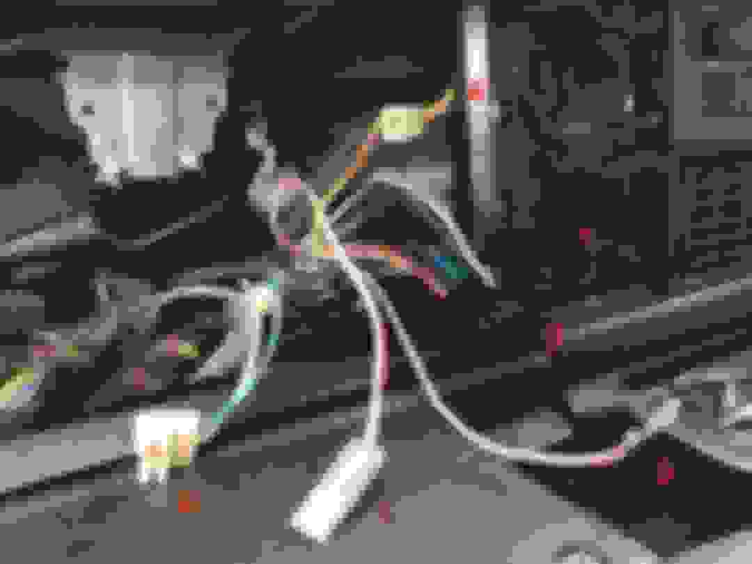
I had to fix the odometer on my new '92 240 Wagon. Being inexperienced (and perhaps not too bright) I failed to make note of what wires went to what plugs. After fixing the odometer and getting everything back together I found myself unable to get the instruments to "wake up." I know others have this issue so I thought I'd both ask here and do it in a way that will remain as a guide to others. So, here are the wires in my car:
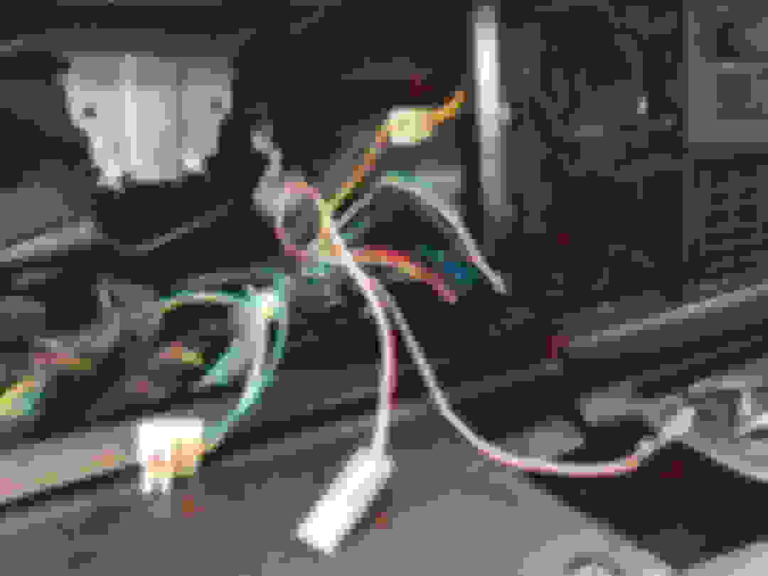
And here is the back
Plugs 1 and 2 are obvious, and I knew enough to not mess with the plug under the skull and bones less I kill the speedo, but that leaves wires 3-6 and plugs a-d. Note that I don't have a tach. That's a clock next to the speedo.
My guesses are:
3 -> c
4 -> d
5 -> b
6 -> a
Can some kind soul verify for me and everyone else which wires go where?
Last edited by leohtbaere; 04-26-2018 at 01:32 PM.
the red-white wire is ONLY if you have a tachometer, otherwise its left disconnected.
indeed, the full circle connector (31 in the drawings) and 'smile" (32 in the drawings) are obvious.
unlabeled on your drawing is the edge connector on the back of the speedometer, just right of your 'skull', that gets a 3 pin right angle connector with blue, green-white, and black wires (top to bottom), which would be your '6'.
'd' in your drawing gets the yellow-red wire '4' for the upshift indicator
'c' is for the glowplug light on a diesel, I doubt you have one (they were awful VW engines).... oh, is yours a manual? is wire '3' PINK-white not red-white (?hard to tell in pic), IF its pink-white, that goes in "C"
wire '5', red/white, is the timing signal for a tachometer, and should not be connected. it comes directly off ignition coil pin 1...
your clock doesn't look anything like the wiring diagrams, they show three spades like...
| _ |
where the left one (as seen from the back of the speedo) gets the brown wire from the dashboard dimmer, the bottom one gets a white wire with always-on clock power (labeled 30 in the diagrams.... but wait, this white wire goes to the circular connector pin 9 so must be wired internally), and the right one (labeled 31 on the diagrams) gets a black ground wire which is likely your "A". .... OH, that 3 blade connector I drew, thats for the separate clock when you have a tach, man they made this confusing...
so... I think that black wire "A" goes on that spade lug "B"
Power to the entire cluster comes in on your #6 wire which should be connected to the edge connector of the speedometer as noted by Pierce. If you still are not getting any power to the cluster with that (and the other wires connected as Pierce indicated), then check that plastic little circuit board that goes between the two screws in the center top of your picture. That acts as a fuse for the cluster. Make sure there is continuity between those two screws.
Yes! You are absolutely correct on all counts. I must have pulled the black clock wire out by mistake when I was taking it out of the dash. I put everything as you suggest and all is well. Thanks for the help!
In the interest in making this all clearer for other users, I've redone the diagrams. NOTE: my car is a '92 240 with an automatic transmission and gasoline engine, and this wiring is most appropriate for cars of that configuration
I hope this helps others. Thanks to all who helped me!
I'm having a similar problem. I have a 91 240 sedan with the k9800 cluster. My check engine light will not come on, I've swapped with a known good bulb, replaced the processors. and then it hit me, I'm looking at the back of this cluster, mine is missing the lug, figure c. I have the pink/white wire with spade terminal. Is there another location that it connects to?
near as I can tell looking at my somewhat fuzzy copy of the 1991 wiring diagram, the CEL pink/white wire connects to '235' which is that female spade connector below and between the white speedo block, and the black clock-or-tach in that picture above.
the other end of the wire forks to both the ECU and ICU diagnostic ouputs (what electronics folks would call a 'wire or' circuit... either CU can pull the circuit to ground to light the indicator).
kinda looks like its riveted? whats the condition of the solder pad on the other side of the hole? you'll probably have to take the whole instrument panel apart to access it,,, you might even be able to use a brass screw and nut instead of solder.
In the interest in making this all clearer for other users, I've redone the diagrams. NOTE: my car is a '92 240 with an automatic transmission and gasoline engine, and this wiring is most appropriate for cars of that configuration
I hope this helps others. Thanks to all who helped me!
This scheme helped me solve the problem! Thanks a lot, greetings from Italy!
the red-white wire is ONLY if you have a tachometer, otherwise its left disconnected.
indeed, the full circle connector (31 in the drawings) and 'smile" (32 in the drawings) are obvious.
unlabeled on your drawing is the edge connector on the back of the speedometer, just right of your 'skull', that gets a 3 pin right angle connector with blue, green-white, and black wires (top to bottom), which would be your '6'.
'd' in your drawing gets the yellow-red wire '4' for the upshift indicator
'c' is for the glowplug light on a diesel, I doubt you have one (they were awful VW engines).... oh, is yours a manual? is wire '3' PINK-white not red-white (?hard to tell in pic), IF its pink-white, that goes in "C"
wire '5', red/white, is the timing signal for a tachometer, and should not be connected. it comes directly off ignition coil pin 1...
your clock doesn't look anything like the wiring diagrams, they show three spades like...
| _ |
where the left one (as seen from the back of the speedo) gets the brown wire from the dashboard dimmer, the bottom one gets a white wire with always-on clock power (labeled 30 in the diagrams.... but wait, this white wire goes to the circular connector pin 9 so must be wired internally), and the right one (labeled 31 on the diagrams) gets a black ground wire which is likely your "A". .... OH, that 3 blade connector I drew, thats for the separate clock when you have a tach, man they made this confusing...
so... I think that black wire "A" goes on that spade lug "B"
Hello, I recently purchased a 1984 Volvo 245 and would appreciate some clarification. Wire #5 was said to be the tachometer signal wire and comes directly off ignition coil pin #1. As I look in the engine compartment, I noticed a single wire coming out of the firewall with insulation and has a male spade connector at the end. The wire is green in color. See pic attached. Should this connect to the coil? Or is there another wire? I also noticed that this wire is a bit short and does not reach the coil. THe male spade connector is throwing me off as well but it is green. Please advise.
I believe thats a test connector. I am not sure what that specific one is for... I know there's a blue wire on a single spade lug, thats for a remote starter, and at least on some cars, there's a test point to disable the idle control system so you can manually adjust teh base idle speed.
hmmm, 1984 wiring diagrams for the LH-II injection system, show a green wire with a spade lug to the oxygen sensor, this is typically right around the windshield wiper motor on the passenger side of the firewall in the engine compartment. They show the wire at the coil #1 is grey, and they don't show any tachometer at all? oh, no, they show a black wire from coil #1 to the tach. guess the red/white wire was in later cars only...
Thanks Pierce, I actually do have a green wire connected to the oxygen sensor on the passenger side. I do have a red/white wire that i connected to the Tach. I guess I will find out if the wiring is connected correctly once I fire up the car in a few days, hopefully.
If someone has an 84, would you mind taking a look at which wires are connected at the coil and if you have a green wire with a male spade on the driver side coming out of the firewall along with the main harness? please. Thank you.
 04-26-2018, 01:29 PM