Volvo 240 Fusebox Update (the Snake Part IV or so)
#1
 08-03-2014, 08:42 PM


Join Date: Jun 2011
Location: West Virginia
Posts: 293
Likes: 0
Received 0 Likes
on
0 Posts
Howdy all:
I have decided I want to update my fuse box in my 1991 Volvo 240. I want to move away from these darned torpedo fuses and to the ATC/ATO fuse style.
We'll get the arguing out of the way to begin with. Why do I want to do such a difficult task? 1) Torpedo fuses haven't been very reliable in my experience. I've had absolutely zero corrosion issues with any ATO style fuses. In fact, Volvo wasn't overly fond of them either, because by the 700 series, they started using ATO fuses. The torpedo is an old design, and ATO is simply better. 2) Torpedo fuses are not that easy to get ahold of. Sure, they are there on the internet, which is fine and dandy if I have a fuse problem at home and can live without that fuse (or make do) for a few days. But this is my only car, and so if i'm driving halfway across the country, and have a problem, and it turns out my spare fuses is a lemon or somehow I forgot that, It would be nice to just stop in an ordinary auto parts store and get the needed fuse. 3) I have a few accessories--mainly my driving lights. Yes, they use ATO fuses. So if carrying spare fuses (which I generally do, mind you) it adds to the number of fuses I need. 4) I don't like the terminals on the torpedo fuses. It is rather easy to get a jolt on them. Certainly, you don't have to... but again, we've designed a system that makes it darned difficult to get shocked if you want to. Why not go with that?
Now, I make no illusions about this being an easy job, but I don't know that it should be super difficult. So this comes to my first question: Does anyone know of anyone who has done this? All the searches i've done have lead me to threads where the questioner is talked out of doing it. Has anyone NOT been talked out of it? If so, have they talked at all about how they did it?
The first challenge I see is finding or creating a fusebox to fit. I like the linear format, and want to keep it. I also want to keep it in the same location. Most 16 fuse boxes are two side by side rows of 8. I'm not so into that. But I have found individual rows of 8, and think two of those one over the other might be the ticket. If anyone has ideas on where to source this, or a better idea, I'm all ears.
The second challenge I see is ensuring that the fuses are all switched at the right time. And this may deal with the way I work with the above challenge. It seems like more fuseboxes I find online are "Easy wire up" systems, where it looks like you have 1 tap that powers all the fuses. and an out for each fuse. Obviously this will not work. If I could find something that would let me jumper the fuses individualy, that would be ideal. However, I also recognize that I may have to alter the way I get my fuseboxes if that is not possible. For instance, the first 3 fuses are all from the same power source, so perhaps one box that holds 3 fuses with a common source would work. Then there are 2 individual fuses and then 5 that are all switched from the key. So maybe a 5 holder fuse thing would work, and arrange all these end to end to create what I need. Anyway, I'm appealing to anyone with knowledge sourcing these types of parts or who has built their own fuse boxes. I may have to create what I want from the ground up... but I can live with that too.
Anyway... As with other projects, I'll post progress here, as well as my research and findings.

#3
08-03-2014, 10:15 PM

note the way the factory 240 fuse panel is wired, there are 3 connectors to the right of each fuse. the rightmost connector goes to the leftmost fuse clip, and this is the power input, while the middle and leftmost connector goes to the right side fuse clip, and these are the fuse output.
at least on most of the later 240s, fuses 1-2-3 have their input side wired together, fuse 4, and 5 are discrete, fuse 6-7-8-9-10 are wrired together, fuse 11-12-13 are ganged, 14 is standalone, and 15-16 are wired together.
if you could find a fuse panel with 16 discrete blade fuse holders with 2 spades on each side, you could simulate this pretty easily by bridging the input sides of 1-2-3, 6-10, 11-13, and 15-16. the catch is, the input spade lugs would likely be an inch or so over from where they are on the 240's original panel, and the existing harness wires might not reach it that easily.
fuses 1-2-3 are powered in accessory and run, 6-10 are always powered, 11-13 are powered in run and start, and 15-16 are powered by the headlight switch parking light circuit.
catch-22, all the fuse holders I found on some quick searches only have one spade lug on each side. or they have terminal strip screws. typical 10-fuse holder...
#4
08-06-2014, 11:00 AM
Join Date: Jun 2011
Location: West Virginia
Posts: 293
Likes: 0
Received 0 Likes
on
0 Posts
Yeah, the whole single spade lug system is problematic. Below, for easy reference, is how my fusebox is wired up. Notice that the 6th one down is independent--goes direct from battery to fuel pump relay. But, as both are always powered... I wonder why they ran a separate wire for that fuse?
What I am hoping to do is get to a junkyard, and take out & pull apart the fusebox so I can get a better look at it. Also get a sense of the space I'll have (or lack thereof).
I am thinking I may use a few gang fuse boxes put together, and then a couple of independant ones. Still just thinking this through...
#5
08-06-2014, 12:52 PM
I should have clarified, the specifics vary per year.
anyways, I just stock up on those ceramic/copper/brass fuses, often sold as "mercedes w123/w124 fuses" as 1970s-80s-early 90s Mercedes E class cars used the same things, and clean the contacts, and put a bit of deoxit or silicone grease on the ends of the fuses to keep oxides out. haven't had any problems since. spare fuses are in the glovebox at all times.
anyways, I just stock up on those ceramic/copper/brass fuses, often sold as "mercedes w123/w124 fuses" as 1970s-80s-early 90s Mercedes E class cars used the same things, and clean the contacts, and put a bit of deoxit or silicone grease on the ends of the fuses to keep oxides out. haven't had any problems since. spare fuses are in the glovebox at all times.
#6
03-04-2015, 01:11 PM
Join Date: Jun 2011
Location: West Virginia
Posts: 293
Likes: 0
Received 0 Likes
on
0 Posts
Well, It has been a long time since I've posted on this, but the project has been in the back of my head for a while. And I've done a fair amount towards a new fusebox. So.... a few months back (about the coldest day we had in December around here) I found myself in a junkyard with 3 Volvo 240s. As they've been getting rather sparse, I availed myself of them. I pulled out the fuse box from one, because I wanted to get a chance to really study how this thing was setup without disabling my car. So, I've photos to share of that.
Below is the fuse box. I have removed all the fuses.

This is a good look at the back of the panel. Specifically the 6 terminals on the right of picture above.

Electrically, it looks like this:

The top/outer terminals (outer if installed on the car) are the side that is coming off the fuse. The inner/bottom terminal is the power form the main power rail or ignition.
You can almost see that in this picture.

The final thing to understand how this fuse box is setup is how the power is linked.

In the above picture, the orange arrows show the gap between units that power the fuses. On the right, underlined in green, you can see a gang of 3, on the left with blue is a gang of 2 and the double underlined in red one is independent of any other fuses.
So, on the whole, starting from the top, you have a gang of 3, 2 independents, a gang of 5, then what is shown above, a gang of 3 a single and a gang of 2 to finish off things. This almost conforms to what I posted a few entries up. Notice though that in the diagram above, the gang of 5 is a gang of 4 + and independent wired with it. Doesn't really matter--it is electrically the same.
The final observation I wanted to make about this fuse panel is that it is pretty thin. Most options I've found tend to have blades for the fuses off either side. This isn't a great option if I want to find a fuse box that will be accessible in mostly the same ways.
Anyway, I'll post this and then move to talking about a suitable replacement.
Below is the fuse box. I have removed all the fuses.
This is a good look at the back of the panel. Specifically the 6 terminals on the right of picture above.
Electrically, it looks like this:
The top/outer terminals (outer if installed on the car) are the side that is coming off the fuse. The inner/bottom terminal is the power form the main power rail or ignition.
You can almost see that in this picture.
The final thing to understand how this fuse box is setup is how the power is linked.
In the above picture, the orange arrows show the gap between units that power the fuses. On the right, underlined in green, you can see a gang of 3, on the left with blue is a gang of 2 and the double underlined in red one is independent of any other fuses.
So, on the whole, starting from the top, you have a gang of 3, 2 independents, a gang of 5, then what is shown above, a gang of 3 a single and a gang of 2 to finish off things. This almost conforms to what I posted a few entries up. Notice though that in the diagram above, the gang of 5 is a gang of 4 + and independent wired with it. Doesn't really matter--it is electrically the same.
The final observation I wanted to make about this fuse panel is that it is pretty thin. Most options I've found tend to have blades for the fuses off either side. This isn't a great option if I want to find a fuse box that will be accessible in mostly the same ways.
Anyway, I'll post this and then move to talking about a suitable replacement.
#7
03-04-2015, 01:43 PM
Join Date: Jun 2011
Location: West Virginia
Posts: 293
Likes: 0
Received 0 Likes
on
0 Posts
So, the trick to finding a suitable replacement is finding a thin and long-ish oriented fuse box. Unfortunately, it seemed that most of the fuse boxes I looked at were boxy, or square in setup with multiple rows. Definitely not what I needed. Until one day I had the brilliant idea to google, "long thin fuse box" in the image search. Guess what? BMWs often use a long thin fuse box. So, looking around on ebay, I found one at a decent price, and purchased it. EDIT: It was out of a 2001 750 iL, the fuse box in the trunk, in case anyone wanted to know. Other would probably work also. END EDIT
This is how it came. I figured I'd have to do some modifications.

However, I had to do less than I thought. (so far) All one has to do as press down on this little tab on the top and bottom, and the black portions slips out the white portion.


So, now a good look at the front and back. You can see the positions for the fuses.


This block can accept 29 fuses, however, it is only wired with the contacts for 14 presently. Yep, I need... wait for it... 16! So, one thing I'll have to do is figure out how/where to get some more of the contact portions for this thing. I have some leads. This guy [ BMW E32 - Rebuilding the Fusebox ] shows how he pulled the innards out the back of a fuse block. It is pretty typical, but I've not done it yet. Note: there is a white rod one must pull out of the black element that hold everything in place in addition to the usual locking pin that goes with these sorts of things.
As of now, I've not gotten any out yet, but I want to re-arrange things a bit so that the fuse order is essentially the same, and thereby, I don't have to change the fuse schedule.
Anyway, that is where I am at the moment I have two challenges to overcome at the moment: Figure out how to remove fuse contacts which will probably only require some ingenuity and a small screw driver. (I don't have the latter at the moment.). Second, I need to find more fuse contacts. A I may be able to get some out of a local junkyard, but rumor is that BMW and VW use the same fuse contacts. Meaning, it may not be that difficult to source online or at my local auto parts store. FCP might even be worth a call--they're generally pretty helpful.
That is where I am at the moment. It may be a while before I get more work done, but putting a modern fuse box in a 240 looks like it is well on it's way to happening.
This is how it came. I figured I'd have to do some modifications.
However, I had to do less than I thought. (so far) All one has to do as press down on this little tab on the top and bottom, and the black portions slips out the white portion.
So, now a good look at the front and back. You can see the positions for the fuses.
This block can accept 29 fuses, however, it is only wired with the contacts for 14 presently. Yep, I need... wait for it... 16! So, one thing I'll have to do is figure out how/where to get some more of the contact portions for this thing. I have some leads. This guy [ BMW E32 - Rebuilding the Fusebox ] shows how he pulled the innards out the back of a fuse block. It is pretty typical, but I've not done it yet. Note: there is a white rod one must pull out of the black element that hold everything in place in addition to the usual locking pin that goes with these sorts of things.
As of now, I've not gotten any out yet, but I want to re-arrange things a bit so that the fuse order is essentially the same, and thereby, I don't have to change the fuse schedule.
Anyway, that is where I am at the moment I have two challenges to overcome at the moment: Figure out how to remove fuse contacts which will probably only require some ingenuity and a small screw driver. (I don't have the latter at the moment.). Second, I need to find more fuse contacts. A I may be able to get some out of a local junkyard, but rumor is that BMW and VW use the same fuse contacts. Meaning, it may not be that difficult to source online or at my local auto parts store. FCP might even be worth a call--they're generally pretty helpful.
That is where I am at the moment. It may be a while before I get more work done, but putting a modern fuse box in a 240 looks like it is well on it's way to happening.
Last edited by zjinqui1k; 03-04-2015 at 01:49 PM. Reason: Clarification
#8
03-06-2015, 09:10 PM
Join Date: Jun 2011
Location: West Virginia
Posts: 293
Likes: 0
Received 0 Likes
on
0 Posts
Well, having the right tools for the right job makes a big difference. I haven't had a decent set of jewel screwdrivers in a while. So, I procured one today, and got started.
Getting the contacts out of the fuse block was not terribly difficult. First, there is a plastic retaining piece that holds contacts in place. This is pictured below:

Removing the contacts is still a little difficult. In addition to the plastic retaining support, each contact has two barbs that hold in in place.
A picture will probably illustrate this better than words.

One barb is visible in this picture, but there is another one below it.
By inserting a jewel screwdriver down into the holes above and below the contact, you can bend the barbs out of the way, and it will slide out the back. The picture below shows the holes one would need to use to release the pictured fuse contact.

If you've ever taken apart any portion of a volvo wiring harness, and re-used the connectors, the procedure is essentially the same, just these fuse contacts use two barbs instead of 1. It is not particuarly, easy, but when it comes out, there's not too much problem.
Getting the individual connectors out was pretty easy. But the supply side is a bit more tricky.
They are essentially 2-7 of these individual contacts mounted together. So, one must loosen all of them, and get it out. I started at the top, and slowly pulled them out as they came loose, and finally when I got to the bottom, the whole thing would come out.
Here are the results:

So... as you can see, I have two gangs of 7, one gang of 5 and one gang of 2 for multiple power connections. I'm going to have to adjust this a bit. I just need two gangs of 3 and one gang of 4, and a gang of two. I should be able to cut and splice to make this work well enough. Still, I need some additional individual connectors. So, that's my next object--off to the internet to see what I can find.
Getting the contacts out of the fuse block was not terribly difficult. First, there is a plastic retaining piece that holds contacts in place. This is pictured below:
Removing the contacts is still a little difficult. In addition to the plastic retaining support, each contact has two barbs that hold in in place.
A picture will probably illustrate this better than words.
One barb is visible in this picture, but there is another one below it.
By inserting a jewel screwdriver down into the holes above and below the contact, you can bend the barbs out of the way, and it will slide out the back. The picture below shows the holes one would need to use to release the pictured fuse contact.
If you've ever taken apart any portion of a volvo wiring harness, and re-used the connectors, the procedure is essentially the same, just these fuse contacts use two barbs instead of 1. It is not particuarly, easy, but when it comes out, there's not too much problem.
Getting the individual connectors out was pretty easy. But the supply side is a bit more tricky.
They are essentially 2-7 of these individual contacts mounted together. So, one must loosen all of them, and get it out. I started at the top, and slowly pulled them out as they came loose, and finally when I got to the bottom, the whole thing would come out.
Here are the results:
So... as you can see, I have two gangs of 7, one gang of 5 and one gang of 2 for multiple power connections. I'm going to have to adjust this a bit. I just need two gangs of 3 and one gang of 4, and a gang of two. I should be able to cut and splice to make this work well enough. Still, I need some additional individual connectors. So, that's my next object--off to the internet to see what I can find.
#9
03-06-2015, 09:42 PM
Join Date: Jun 2011
Location: West Virginia
Posts: 293
Likes: 0
Received 0 Likes
on
0 Posts
Searching around on the web:
These types of contacts are called, "double leaf spring contact." Or such is the BMW designation. It appears that VW and Audi use pretty much the same contact. For BMW, VW or Audi, they typically sell them pre-crimped on a wire so you can just splice it in. However, you can also find just contacts ready to crimp. I don't have the correct crimper, but I am handy with a soldering iron, so that's the route I plan to take.
The pn '̶m̶ ̶o̶r̶d̶e̶r̶i̶n̶g̶ ̶i̶s̶ ̶N̶9̶0̶6̶8̶4̶5̶0̶5̶.̶ ̶T̶h̶e̶y̶'̶r̶e̶ ̶9̶9̶�̶ ̶e̶a̶c̶h̶.̶ EDIT: This is the wrong size. Do not order these. END EDIT. Not the cheapest. One could probably go to a junkyard and raid some BMW/VW/Audi's fuse box for these, but I'm going to order a few this way, just to see.
That's all for now.
Last edited by zjinqui1k; 03-10-2015 at 03:40 PM. Reason: correct bad info.

#11
03-10-2015, 03:42 PM
Join Date: Jun 2011
Location: West Virginia
Posts: 293
Likes: 0
Received 0 Likes
on
0 Posts
#12
03-10-2015, 05:20 PM
volvo parts for what I think are blade fuse sized crimps...
the following three have the crimp part pointing up when the fuse is lying on its flat side...
978256 (for 0.3-0.6mm� wire)
978257 (for 0.75-1.5mm� wire)
978258 (for 1.5-2.5mm� wire)
the following three have the crimp part pointing to the side when the fuse is on its flat side
970776 - 0.5-1.5mm�, LG 18.8mm
970778 - 0.5-1.5mm�, LG 21.0mm
970779 - 1.1-2.5mm�, LG 21.0mm
no idea what LG means. all wire sizes in mm squared.
#13
04-01-2015, 12:53 PM

Junior Member
Join Date: Apr 2015
Location: Shoreline, WA
Posts: 26
Likes: 0
Received 0 Likes
on
0 Posts
I am interested to see this get resolved. Blade fuses are on my longterm to-do list. But here's an idea if you find yourself working with a fuse box with a single quick disconnect or screw terminal per fuse:
Use a connector that is for a wire size larger than the wire you are using and crimp two wires into each terminal.
Use a connector that is for a wire size larger than the wire you are using and crimp two wires into each terminal.
#14
04-02-2015, 04:41 PM
Join Date: Jun 2011
Location: West Virginia
Posts: 293
Likes: 0
Received 0 Likes
on
0 Posts
Oh, i'm still working on it. Just, other things have taken priority for a while. I ended up just getting another BMW fuse box for like $20 on ebay, that way I have 1) lots of fuses, 2) lots of 'double leaf spring contacts' and 3) a spare couple of blocks if I mess this one up.
I haven't worked on it since I received this second BMW fuse box, but when I get time, I will, and post the results.
I haven't worked on it since I received this second BMW fuse box, but when I get time, I will, and post the results.
#15
03-27-2016, 07:01 PM
Join Date: Jun 2011
Location: West Virginia
Posts: 293
Likes: 0
Received 0 Likes
on
0 Posts
Howdy Folks! This project has been on the back burner for way too long, but spring break and warm weather have made all things possible!
I took apart the second BMW fusebox, and got out many of their contacts.
Building the Fusebox: The Complication
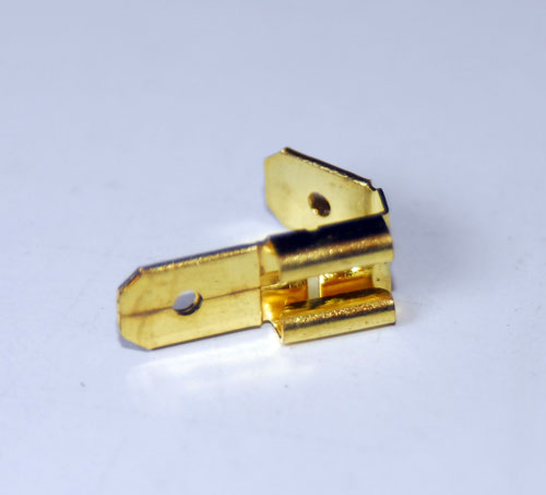
As I got back into this project, I realized that there would be a few complications. As has been shown in my previous diagrams, there is a single input blade for any given fuse, but two output blades. This makes for easy connections in the fusebox they set up, but in the BMW style fusebox, it rather presumed that every wire coming into the fusebox would have its own fuse. This mean that I had to solder together and create a number of Y connectors. Additionally, I had to make sure that the gauge of wire I was using was sufficient to carrying the current. This meant that some of the Y connectors were rather large. Following is an example:

The red arrow is where the fuse contacts, and slip into the fusebox, and the blue arrows are where the output for the fusebox are.
Building the Fusebox: The Feed Side
Here is the scheme I used for the input power. I expanded a number of the multi-gang connections to allow for my own future expansion of accessories. (Such as driving lights, various gauges, etc.)

The top set are switched from the ignition. It only needed 3, but I had room, so I have two more positions for potential accessories there.
The next three were various single item , then the next large gang is the always on set. This I also expanded for potential accessories.
Next, with the green wire, is another switched set from the ignition, which I also expanded.
The single is for the rear fog lamps, and the final double gang is for the instrument and rear end lighting.
This ended up looking like this:

Actually, there were two errors, indicated by the arrows. I didn't catch them until later, and the pictures of the subsequent fixes are not clear because I have more of the fusebox put together.
At the blue arrow, I forgot to add one more input lead. Opps. I popped out the bank of fuseholders below it and fixed it easy enough. At the pink arrow, there is kind of a strange situation. The fusebox uses the connection there as not only an input for the fuses, but a junction to power other things. power from the main bus comes in from a brown wire, but power to the light switch goes out on a green/red wire. I forgot to put a second lead on the power input. I fixed it with the following modification:

Not the prettiest solder, I'll admit, but electrically good. I didn't bother insulating it because it ends up in the plastic shield of the fusebox.
Building the Fusebox: The Output Side
That was the easy part. Then, I had to get out the old soldering gun to do a lot more soldering of the Y's i showed above. easy enough to describe, but time consuming. I was also cautious to size the wires so that they would handle the current being put through them. The result of the completely wired fusebox is below (except for errors previously noted):

A few notes on this: Each barb on the fuse insert was typically bent up from when I removed the fuse insert initially. I re-bent these barbs to work more effectively before I re-inserted.
Also, in one of my eariler posts, I noted that there is a white retaining pience of plastic that I had to remove. When I was done with the fusebox, I re-inserted this, further securing the fuse contact inserts. This is fairly important, but none of my pictures show this well.
Building the Fusebox: Mounting to the Car
Then, I had to figure out how to mount it to the car. I ultimately decided that a thin piece of wood would work to give the screws something solid to hold against, rather than the plastic form of the fusebox. I epoxied the fusebox to the piece of wood, essentially a paint stiring stick properly trimmed with added holes. It looked like this:

That takes care of the top screw. but the bottom one needs some work. It is worth noting here that when I layed out my fusebox, I was conscious that I'd have to put a screw through the location that might otherwise be used for fuses. Obviously, I avoided those locations. Using a drill at very low speeds, I very carefully created a whole in the plastic. If you do this, be very careful, because if you are not, you will bust up the plastic of the fusebox, and you'll have to find a new one. Also note that I had to trim off the fuse insert retaining bar a little bit to get the screw to fit properly. I did this very carefully, as I didn't want to break it, nor did I want to live without this piece. None of the pictures show this very well.
The result looked as follows:

Installing the Fusebox
Then, on to wiring the box up. This was pretty straight forward, but there is one important note. The following picture helps explain:

All of the outgoing connections looked like the connection at the end of the purple arrow: they were uninsulated. This worked fine when all the wires were held rigidly in place as the old fusebox did, but my Ys and pigtails made it a real possibility that they would short out when bundled together against one another. So, I did what is shown with the Red Arrows: Applied some shrink wrap to the connections so they could not easily short out. The green arrow shows the feeds for the fusebox. You can see that they were already insulated.
Here we have the fusebox all wired up.

Note here that I have labeled the fuses so that they correspond with the fuse legend on the panel cover. This was to keep confusion to a minimum when I work on the car again. And since months can pass before I work on it again, taking copious notes and keeping my work clear has been very helpful.
It is at this point that it has probably occured to you that there is an awful lot of extra wire in this new arrangement. While there are only an inch or so per each Y, all of this adds up. Further, a lot of what is there has a lot of solder in it, so it isn't very easy to bend most of these wires. The mess ends up looking something like this when fully mounted:

It doesn't fit super well underneath the plastic cover. I could cut wires... but I generally prefer to avoid that. If need be, right now, I can go right back to that crappy old fusebox. Once I cut the wires, there is no return. Well, at least not easily. But it took a lot of jamming and craming to get the plastic cover back on, and in truth, it really doesn't fit well. It tends to bulge a bit. Here's what it looks like:

It doesn't look bad, and nobody else would probably notice, especially once the cover is on. But the fit is only okay because of the wires.
Some Notes on Fuses
In the 240, it calls for 8, 16 and 25 amp fuses. While these were common designations once upon a time, they are not today, and not in ATO style fuses. Most of the fuses I have came from the BMW fuseboxes I cannibalized. By and large, I used 7.5 amp fuses in place of 8 amp fuses, and 15 amp fuses in place of 16 amp fuses. 25 amps works straight across--we have them in both styles. But as you can see, I didn't have quite enough 7.5 amp fuses. So in some cases, with equipment I deemed to be less sensitive, I used a 10 amp fuse in place of a 7.5 amp fuse. And although I plan on switching them out for 7.5 amp fuses, there is probably little need. Also, as 7.5 amp is slightly undersized, If I find they keep blowing when I put a heavy load on them, I'll probably jump up to 10 amp anyway. Similarly, if the 15 amp fuses blow, I'll probably upgrade to a 20 amp. That said, I doubt that will ever happen. I'd probably bet money on that. (But not much. I'm not a big one for betting.)
Final Analysis & Results
I am extremely pleased with my results so far. I have a volt meter in my car, and I found it odd how it seemed to vary quite a bit. I figured it was that the alternator put out more power when the battery required more to recharge, and this was more needed in the winter. But if i thought about this for a moment, I would have realized that this doesn't make a whole lot of sense: while the current might vary somewhat depending on need, the output from the alternator in volts should be pretty steady. With the new fusebox, the volt meter doesn't wander at all, and just comes up to one place, and stays there. It also read about half a volt higher across the board (including when the car is off, reading battery only voltage, and when the alternator is running). It seems the corrosion in the old fuses/fusebox gave me about about a half a volt drop on the circuit the meter monitored. It seems likely lots of my electrical system suffered from a small voltage drop.
Some results will take time before they become apparent. there were various electrical gremlins that seemed to come and go, that i could often alleviate by spinning the fuses. It will be interesting to see if the clock works consistently now; I've long had trouble with it working all the time (and I rather like having a working clock in the car). We shall see if it randomly fails like it used to.
The fit is not perfect in the car. I may get another 240 soon, and when I do, I will try to re-think this to see if I can come up with a better solution for handling all the wires. I also wonder if I could create my own piece of textured plastic, or maybe cut one up and use some fiberglass to re-create one in my own image that would better accommodate the additional wires.
The bottom line is that I am very pleased with the modification. We shall see how it stands the test of time.
I took apart the second BMW fusebox, and got out many of their contacts.
Building the Fusebox: The Complication
As I got back into this project, I realized that there would be a few complications. As has been shown in my previous diagrams, there is a single input blade for any given fuse, but two output blades. This makes for easy connections in the fusebox they set up, but in the BMW style fusebox, it rather presumed that every wire coming into the fusebox would have its own fuse. This mean that I had to solder together and create a number of Y connectors. Additionally, I had to make sure that the gauge of wire I was using was sufficient to carrying the current. This meant that some of the Y connectors were rather large. Following is an example:
The red arrow is where the fuse contacts, and slip into the fusebox, and the blue arrows are where the output for the fusebox are.
Building the Fusebox: The Feed Side
Here is the scheme I used for the input power. I expanded a number of the multi-gang connections to allow for my own future expansion of accessories. (Such as driving lights, various gauges, etc.)
The top set are switched from the ignition. It only needed 3, but I had room, so I have two more positions for potential accessories there.
The next three were various single item , then the next large gang is the always on set. This I also expanded for potential accessories.
Next, with the green wire, is another switched set from the ignition, which I also expanded.
The single is for the rear fog lamps, and the final double gang is for the instrument and rear end lighting.
This ended up looking like this:
Actually, there were two errors, indicated by the arrows. I didn't catch them until later, and the pictures of the subsequent fixes are not clear because I have more of the fusebox put together.
At the blue arrow, I forgot to add one more input lead. Opps. I popped out the bank of fuseholders below it and fixed it easy enough. At the pink arrow, there is kind of a strange situation. The fusebox uses the connection there as not only an input for the fuses, but a junction to power other things. power from the main bus comes in from a brown wire, but power to the light switch goes out on a green/red wire. I forgot to put a second lead on the power input. I fixed it with the following modification:
Not the prettiest solder, I'll admit, but electrically good. I didn't bother insulating it because it ends up in the plastic shield of the fusebox.
Building the Fusebox: The Output Side
That was the easy part. Then, I had to get out the old soldering gun to do a lot more soldering of the Y's i showed above. easy enough to describe, but time consuming. I was also cautious to size the wires so that they would handle the current being put through them. The result of the completely wired fusebox is below (except for errors previously noted):
A few notes on this: Each barb on the fuse insert was typically bent up from when I removed the fuse insert initially. I re-bent these barbs to work more effectively before I re-inserted.
Also, in one of my eariler posts, I noted that there is a white retaining pience of plastic that I had to remove. When I was done with the fusebox, I re-inserted this, further securing the fuse contact inserts. This is fairly important, but none of my pictures show this well.
Building the Fusebox: Mounting to the Car
Then, I had to figure out how to mount it to the car. I ultimately decided that a thin piece of wood would work to give the screws something solid to hold against, rather than the plastic form of the fusebox. I epoxied the fusebox to the piece of wood, essentially a paint stiring stick properly trimmed with added holes. It looked like this:
That takes care of the top screw. but the bottom one needs some work. It is worth noting here that when I layed out my fusebox, I was conscious that I'd have to put a screw through the location that might otherwise be used for fuses. Obviously, I avoided those locations. Using a drill at very low speeds, I very carefully created a whole in the plastic. If you do this, be very careful, because if you are not, you will bust up the plastic of the fusebox, and you'll have to find a new one. Also note that I had to trim off the fuse insert retaining bar a little bit to get the screw to fit properly. I did this very carefully, as I didn't want to break it, nor did I want to live without this piece. None of the pictures show this very well.
The result looked as follows:
Installing the Fusebox
Then, on to wiring the box up. This was pretty straight forward, but there is one important note. The following picture helps explain:
All of the outgoing connections looked like the connection at the end of the purple arrow: they were uninsulated. This worked fine when all the wires were held rigidly in place as the old fusebox did, but my Ys and pigtails made it a real possibility that they would short out when bundled together against one another. So, I did what is shown with the Red Arrows: Applied some shrink wrap to the connections so they could not easily short out. The green arrow shows the feeds for the fusebox. You can see that they were already insulated.
Here we have the fusebox all wired up.
Note here that I have labeled the fuses so that they correspond with the fuse legend on the panel cover. This was to keep confusion to a minimum when I work on the car again. And since months can pass before I work on it again, taking copious notes and keeping my work clear has been very helpful.
It is at this point that it has probably occured to you that there is an awful lot of extra wire in this new arrangement. While there are only an inch or so per each Y, all of this adds up. Further, a lot of what is there has a lot of solder in it, so it isn't very easy to bend most of these wires. The mess ends up looking something like this when fully mounted:
It doesn't fit super well underneath the plastic cover. I could cut wires... but I generally prefer to avoid that. If need be, right now, I can go right back to that crappy old fusebox. Once I cut the wires, there is no return. Well, at least not easily. But it took a lot of jamming and craming to get the plastic cover back on, and in truth, it really doesn't fit well. It tends to bulge a bit. Here's what it looks like:
It doesn't look bad, and nobody else would probably notice, especially once the cover is on. But the fit is only okay because of the wires.
Some Notes on Fuses
In the 240, it calls for 8, 16 and 25 amp fuses. While these were common designations once upon a time, they are not today, and not in ATO style fuses. Most of the fuses I have came from the BMW fuseboxes I cannibalized. By and large, I used 7.5 amp fuses in place of 8 amp fuses, and 15 amp fuses in place of 16 amp fuses. 25 amps works straight across--we have them in both styles. But as you can see, I didn't have quite enough 7.5 amp fuses. So in some cases, with equipment I deemed to be less sensitive, I used a 10 amp fuse in place of a 7.5 amp fuse. And although I plan on switching them out for 7.5 amp fuses, there is probably little need. Also, as 7.5 amp is slightly undersized, If I find they keep blowing when I put a heavy load on them, I'll probably jump up to 10 amp anyway. Similarly, if the 15 amp fuses blow, I'll probably upgrade to a 20 amp. That said, I doubt that will ever happen. I'd probably bet money on that. (But not much. I'm not a big one for betting.)
Final Analysis & Results
I am extremely pleased with my results so far. I have a volt meter in my car, and I found it odd how it seemed to vary quite a bit. I figured it was that the alternator put out more power when the battery required more to recharge, and this was more needed in the winter. But if i thought about this for a moment, I would have realized that this doesn't make a whole lot of sense: while the current might vary somewhat depending on need, the output from the alternator in volts should be pretty steady. With the new fusebox, the volt meter doesn't wander at all, and just comes up to one place, and stays there. It also read about half a volt higher across the board (including when the car is off, reading battery only voltage, and when the alternator is running). It seems the corrosion in the old fuses/fusebox gave me about about a half a volt drop on the circuit the meter monitored. It seems likely lots of my electrical system suffered from a small voltage drop.
Some results will take time before they become apparent. there were various electrical gremlins that seemed to come and go, that i could often alleviate by spinning the fuses. It will be interesting to see if the clock works consistently now; I've long had trouble with it working all the time (and I rather like having a working clock in the car). We shall see if it randomly fails like it used to.
The fit is not perfect in the car. I may get another 240 soon, and when I do, I will try to re-think this to see if I can come up with a better solution for handling all the wires. I also wonder if I could create my own piece of textured plastic, or maybe cut one up and use some fiberglass to re-create one in my own image that would better accommodate the additional wires.
The bottom line is that I am very pleased with the modification. We shall see how it stands the test of time.
Last edited by zjinqui1k; 03-27-2016 at 08:32 PM. Reason: grammatical errors
#17
04-19-2016, 02:08 PM

Wouldn't it be more effective to cannibalize the tangs from the volvo fuse panel and solder them directly to the multi connectors on the BMW panel? All you would need to do is make small cutouts for them and it would eliminate the need for several inches of extra wire shoved behind the panel
#18
04-28-2016, 06:37 PM
Join Date: Jun 2011
Location: West Virginia
Posts: 293
Likes: 0
Received 0 Likes
on
0 Posts
Wouldn't it be more effective to cannibalize the tangs from the volvo fuse panel and solder them directly to the multi connectors on the BMW panel? All you would need to do is make small cutouts for them and it would eliminate the need for several inches of extra wire shoved behind the panel
#20
04-29-2016, 08:55 AM
Join Date: Jun 2011
Location: West Virginia
Posts: 293
Likes: 0
Received 0 Likes
on
0 Posts
Hummm, those would be perfect. And a lot easier than the soldering job I did. What do we call those? I'd probably still need to apply some shrink wrap to the edges of this adapter, but that would improve the situation a lot. I'd shorten up the leads. I'll have to do this in my next iteration.