PCV Breather System Replacement
#1
 09-02-2009, 10:04 PM


I know that there is a previous post with a lot of information on how to service the PCV system on the 850’s but I found that my setup was slightly different and I’ve included some pictures.
I decided it was time to service the system because the motor was showing signs of high pressure in the engine and head (oil on the top of the motor, oil being forced out the crank seal and oil dipstick seal) and I know there are over 200k miles on the motor (although the odometer doesn’t reflect that fact).
Although servicing the PCV system is not beyond the weekend mechanic it is not a quick job by any means. It does give you the opportunity to service or replace several other parts while your in the neighborhood, such as the EGR valve, Throttle Position Sensor, Fuel Pressure Regulator and Starter Motor just to name a few.
Before the actual work on my 850 happened I ordered the replacement parts that I expected that I would need. I ordered mine from FCPGroton.com, they offer a complete PCV Breather system kit which will have the various hoses and clamps as well as the Oil Separator and the Flame Trap. For good measure they also throw in a new Intake Manifold Gasket. I also purchased a new Throttle Body Gasket, a new Vacuum Tree with o-ring, a oil cap gasket and new o-rings and seals for the Fuel Injectors. I already had on hand some vacuum hose, Throttle Body Cleaner and starting fluid.
The tools required are a metric socket set, a set of Torx bits, a CV joint boot clamp pliers (for the new hose clamps on the PCV system), and a jack with stand. A shop light also proved to be very helpful.
And now, the procedure I used to replace the PCV system on my ’94 Volvo 850 (if yours is newer or Turbo it may be slightly different).
1) Disconnect the Negative Battery Cable (should go without saying, but I will say it)
2) Remove and set aside the various trim pieces that will be in your way. The trim piece on the fuel rail just pulls off. The sparkplug wire cover is held on with five T-30 screws. The Idle Air/Throttle Wheel cover is held on with a single T-25 screw, then rock forward off the Idle Air Bracket.

3) Remove the Idle Air Pump – Disconnect the wiring harness from the air pump. Release the rubber retaining strap holding the air pump to the bracket by using a finger on the underside of the bracket to push the rubber tab out of the bracket. Remove the hoses from the Vacuum Tree and the Air Intake. The Idle Air Pump will now lift off. Set the Air pump aside and note the direction of retaining strap on the pump for reinstallation.
4) Remove the Vacuum Tree from the Intake – Release the five small vacuum hoses from the tree and note where they go so you can get them reconnected properly. After removing the 10mm bolt the Vacuum Tree will lift out.

5) Disconnect the throttle linkage connecting the accelerator cable drum to the Throttle body. Note the orientation of the linkage when you remove it and set it aside.
6) Remove the Throttle Drum/Air Pump mounting bracket. The bracket is held down with three 10mm bolts. You do not need to disconnect the accelerator cable, just set the bracket out of the way somewhere in the engine compartment.
7) Remove the Air Duct connecting the Intake of the Throttle Body and the output of the Air Cleaner box – Remove the Flame Trap from the rear of the air duct by rotating it a few degrees to the right and pull out to release the bayonet style base on the Flame Trap (the Flame trap will give you for first glimpse of the PCV system health, mine was clogged with soot and nasty looking stuff). Loosen the clamps holding the air duct to the Throttle Body and the Mass Airflow Sensor using a screwdriver or a 7mm socket, pull off the duct and set aside.
8) Remove the Throttle Body – Disconnect the wiring harness from the Throttle Position Sensor and the two vacuum hoses on the underside of the Throttle Body. There are four 10mm bolts holding the Throttle Body onto the Intake Manifold to remove. Until you are sure all four bolts are identical note where each came from, mine were all the same, yours may not be. Use Throttle Body Cleaner to remove the varnish and deposits from the Throttle Body as well as any part of the old gasket left behind and set aside.

9) Disconnect the breaking system vacuum boost hose from the Intake Manifold.
10) Disconnect the wiring harnesses from the Fuel Injectors and pull it out of the way.
11) Release the fuel pressure in the Fuel Rail by connecting a fuel pressure gage with pressure release to the Schrader valve on the end of the fuel rail. If you don’t have fuel pressure gage or like me yours is in another state right now use a T-10 screw driver wrapped in a rag to release the pressure.

12) Remove the Fuel Rail and Injectors from the Manifold – Remove the T-25 screw from the clamp holding the fuel supply and return lines to the rear of the engine. Loosen the T-25 clamp on the fuel return line from the Fuel Pressure Regulator and remove the rubber hose from the fuel return line. Remove the T-25 screw holding the retaining clip in place on supply side of the Fuel Rail, be very careful not to drop the screw or the retaining clip! With the retaining clip removed pull the supply line out of the Fuel Rail, there likely will be fuel that comes out of the Fuel Rail once you pull the supply line. Remove the two 10mm bolts holding the Fuel Rail and Injectors onto the Intake Manifold. With the bolts removed you can pull on the Fuel Rail to remove it and the Injectors. The o-rings holding the injectors in place should be very tight and some force may be required to remove the Injectors from the Manifold. Check that there weren’t any o-rings or seals left behind.

13) Jack the vehicle and secure with a jack stand.
14) From underneath the vehicle you can access two 12mm bolts that need to be removed, one holds the oil dipstick tube to the underside of the manifold, the other attaches the Intake Manifold to an engine support bracket. Note which is which as oil dipstick retaining bolt is shorter.
15) Loosen the four 10mm bolts on the lower edge of the Intake Manifold where it connects to the engine. After breaking them loose with a box end wrench you should be able to turn them by hand. Loosen them about a quarter inch but do not remove them. One of the lower bolts is very near the thermostat, it is easy to miss and difficult to get to, I used a � inch deep-well socket and about 16 inches of extension so the ratchet would clear the Power Steering Pump.
16) Remove the three 10mm bolts on the upper edge of the Intake Manifold. Note which hole each bolt came from.
17) Now that the Intake Manifold is loose you can get to the two 8mm bolts holding the EGR valve to the underside of the manifold near where the Throttle Body was. These bolts suck to remove and are about a half inch longer than they need to be. Remove the bolts and recover the gasket that sits between the manifold and the EGR valve.
18) Disconnect the head vent hose from the top of the engine.
19) Rock the Intake Manifold forward and lift out starting at the Thermostat end. As you are lifting it out there is a vacuum line running to the choke control that needs to be disconnected and the Head Vent Hose and Flame Trap Hose will need to fed through the manifold. With the Manifold removed clean the injector seats and gasket surfaces with throttle body cleaner, set aside.

20) Mark the position on the Intake Manifold support bracket on the block, then remove the 12mm bolt holding the bracket to the block and allow the bracket to hang out of the way.
21) Remove the clamp on the Crank Vent hose,
22) Loosen the two clamps on the Oil Drain hose using a T-25 screw driver.
23) Remove the two 10mm bolts holding the Oil Separator to the block. Pry the Oil Separator away from the block disconnecting the Crank Vent Hose and the Oil Drain Hose. Discard the Oil Separator and hoses.
24) Blow some compressed air into the Crank Vent, Oil Drain and Head Vent openings to be sure they are clear.
25) Fit the new Head and Crank Vent hoses and the elbow for the Flame Trap hose to the new Oil Separator, tighten the clamps using a CV Joint Boot Clamp Pliers or similar tool.
26) Fit the new Oil Drain hose to the Oil Separator, slide on the new clamps and fit the Oil Trap onto the block. Install the two 10mm bolts that hold the Oil Separator to the block. Tighten the two T-25 screws on the Oil Drain clamps. Fit the Crank Vent hose to the block and tighten the clamp.
27) Double check that all hoses are tight and that all required clamps are installed.
28) Reinstall the Manifold Support Bracket in the marked position; tighten its 12mm bolt.
29) Remove the four lower Intake Manifold bolts, remove and discard the old manifold gasket. Fit a new gasket in place and return the four bolts their spots.
30) Set the Intake Manifold in place on the lower manifold bolts. Feed the new Head Vent and Flame Trap hoses through the manifold, reconnect the vacuum hose to the Choke control.
31) Reconnect the EGR valve to the manifold using its two 8mm bolts. Don’t forget its gasket; tighten the bolts to spec.
32) Install, but do not tighten, the three upper manifold bolts.
33) Install the 12mm bolt connecting the Intake Manifold to the support bracket and the bolt connecting the Oil Dipstick tube to the manifold.
34) Tighten all seven 10mm Intake Manifold bolts to spec.
35) Fit the Head Vent hose to the vent on the head, install and tighten the clamp.
36) Install the Fuel Rail and Injectors onto the Intake Manifold. Some pressure may be required to get the injectors to seat properly. Press the seals into place.
37) Reconnect the fuel return line to the Fuel Pressure Regulator and the fuel supply to the input of the Fuel Rail. Tighten the clamps on the return line and fit the retaining clip and screw into the supply side. Reinstall the retaining bracket and T-25 screw on the rear of the block.
38) Fit the Throttle Body with a new gasket to the Intake Manifold using its four 10mm bolts; tighten to spec. Reconnect the two vacuum lines on the bottom of the throttle body and reconnect the wiring harness to the Throttle Position Sensor.
39) Reconnect the braking system vacuum boost hose.

40) Fit the new Flame Trap into the Air Duct. Reinstall the Air Duct connecting it to the Throttle Body and the Mass Air Flow Sensor on the Air Box. Connect the Flame Trap hose and the smaller vacuum hose to the Flame Trap.
41) Route the Fuel Injector wiring harness to the Injectors and plug them in.
42) Install the Throttle Drum/Air Pump bracket on the manifold using its three 10mm bolts. Reattach the Throttle Linkage; install the screw on the injector wiring retaining harness.
43) Fit the Vacuum Tree to the manifold. Be sure it is fully seated before installing its 10mm retaining bolt. Connect the five smaller vacuum lines to the tree.
44) Install the Idle Air Pump. Connect the two hoses to the Vacuum Tree and the Air Duct. Install the air pump retaining strap, you may need to use a screw driver to help seat the strap. Reconnect the wiring harness to the Idle Air Pump.
45) Reconnect the battery.
46) Start the motor. Note: it will likely be difficult to start the motor due to the fuel system being dry.
47) Check for fuel leaks around the Fuel Rail supply and return lines as well as around the injectors.
48) Check for vacuum leaks. With the motor running I sprayed starting fluid around the Vacuum Tree, Throttle Body, Injectors and the manifold output. Where ever there is a leak the starting fluid will be drawn in and cause the motor to race.
49) As long as there aren’t any fuel or vacuum leaks go for a test drive. It probably indicates another problem with my Volvo but when I went for my test drive about a half mile from home the motor died. After waiting about 5 minutes it started and it hasn’t died on me again nor were any codes stored in the computer.
50) After a few days of driving change the engine oil and filter.
Take your time, be careful and have fun!
I decided it was time to service the system because the motor was showing signs of high pressure in the engine and head (oil on the top of the motor, oil being forced out the crank seal and oil dipstick seal) and I know there are over 200k miles on the motor (although the odometer doesn’t reflect that fact).
Although servicing the PCV system is not beyond the weekend mechanic it is not a quick job by any means. It does give you the opportunity to service or replace several other parts while your in the neighborhood, such as the EGR valve, Throttle Position Sensor, Fuel Pressure Regulator and Starter Motor just to name a few.
Before the actual work on my 850 happened I ordered the replacement parts that I expected that I would need. I ordered mine from FCPGroton.com, they offer a complete PCV Breather system kit which will have the various hoses and clamps as well as the Oil Separator and the Flame Trap. For good measure they also throw in a new Intake Manifold Gasket. I also purchased a new Throttle Body Gasket, a new Vacuum Tree with o-ring, a oil cap gasket and new o-rings and seals for the Fuel Injectors. I already had on hand some vacuum hose, Throttle Body Cleaner and starting fluid.
The tools required are a metric socket set, a set of Torx bits, a CV joint boot clamp pliers (for the new hose clamps on the PCV system), and a jack with stand. A shop light also proved to be very helpful.
And now, the procedure I used to replace the PCV system on my ’94 Volvo 850 (if yours is newer or Turbo it may be slightly different).
1) Disconnect the Negative Battery Cable (should go without saying, but I will say it)
2) Remove and set aside the various trim pieces that will be in your way. The trim piece on the fuel rail just pulls off. The sparkplug wire cover is held on with five T-30 screws. The Idle Air/Throttle Wheel cover is held on with a single T-25 screw, then rock forward off the Idle Air Bracket.
3) Remove the Idle Air Pump – Disconnect the wiring harness from the air pump. Release the rubber retaining strap holding the air pump to the bracket by using a finger on the underside of the bracket to push the rubber tab out of the bracket. Remove the hoses from the Vacuum Tree and the Air Intake. The Idle Air Pump will now lift off. Set the Air pump aside and note the direction of retaining strap on the pump for reinstallation.
4) Remove the Vacuum Tree from the Intake – Release the five small vacuum hoses from the tree and note where they go so you can get them reconnected properly. After removing the 10mm bolt the Vacuum Tree will lift out.
5) Disconnect the throttle linkage connecting the accelerator cable drum to the Throttle body. Note the orientation of the linkage when you remove it and set it aside.
6) Remove the Throttle Drum/Air Pump mounting bracket. The bracket is held down with three 10mm bolts. You do not need to disconnect the accelerator cable, just set the bracket out of the way somewhere in the engine compartment.
7) Remove the Air Duct connecting the Intake of the Throttle Body and the output of the Air Cleaner box – Remove the Flame Trap from the rear of the air duct by rotating it a few degrees to the right and pull out to release the bayonet style base on the Flame Trap (the Flame trap will give you for first glimpse of the PCV system health, mine was clogged with soot and nasty looking stuff). Loosen the clamps holding the air duct to the Throttle Body and the Mass Airflow Sensor using a screwdriver or a 7mm socket, pull off the duct and set aside.
8) Remove the Throttle Body – Disconnect the wiring harness from the Throttle Position Sensor and the two vacuum hoses on the underside of the Throttle Body. There are four 10mm bolts holding the Throttle Body onto the Intake Manifold to remove. Until you are sure all four bolts are identical note where each came from, mine were all the same, yours may not be. Use Throttle Body Cleaner to remove the varnish and deposits from the Throttle Body as well as any part of the old gasket left behind and set aside.
9) Disconnect the breaking system vacuum boost hose from the Intake Manifold.
10) Disconnect the wiring harnesses from the Fuel Injectors and pull it out of the way.
11) Release the fuel pressure in the Fuel Rail by connecting a fuel pressure gage with pressure release to the Schrader valve on the end of the fuel rail. If you don’t have fuel pressure gage or like me yours is in another state right now use a T-10 screw driver wrapped in a rag to release the pressure.
12) Remove the Fuel Rail and Injectors from the Manifold – Remove the T-25 screw from the clamp holding the fuel supply and return lines to the rear of the engine. Loosen the T-25 clamp on the fuel return line from the Fuel Pressure Regulator and remove the rubber hose from the fuel return line. Remove the T-25 screw holding the retaining clip in place on supply side of the Fuel Rail, be very careful not to drop the screw or the retaining clip! With the retaining clip removed pull the supply line out of the Fuel Rail, there likely will be fuel that comes out of the Fuel Rail once you pull the supply line. Remove the two 10mm bolts holding the Fuel Rail and Injectors onto the Intake Manifold. With the bolts removed you can pull on the Fuel Rail to remove it and the Injectors. The o-rings holding the injectors in place should be very tight and some force may be required to remove the Injectors from the Manifold. Check that there weren’t any o-rings or seals left behind.
13) Jack the vehicle and secure with a jack stand.
14) From underneath the vehicle you can access two 12mm bolts that need to be removed, one holds the oil dipstick tube to the underside of the manifold, the other attaches the Intake Manifold to an engine support bracket. Note which is which as oil dipstick retaining bolt is shorter.
15) Loosen the four 10mm bolts on the lower edge of the Intake Manifold where it connects to the engine. After breaking them loose with a box end wrench you should be able to turn them by hand. Loosen them about a quarter inch but do not remove them. One of the lower bolts is very near the thermostat, it is easy to miss and difficult to get to, I used a � inch deep-well socket and about 16 inches of extension so the ratchet would clear the Power Steering Pump.
16) Remove the three 10mm bolts on the upper edge of the Intake Manifold. Note which hole each bolt came from.
17) Now that the Intake Manifold is loose you can get to the two 8mm bolts holding the EGR valve to the underside of the manifold near where the Throttle Body was. These bolts suck to remove and are about a half inch longer than they need to be. Remove the bolts and recover the gasket that sits between the manifold and the EGR valve.
18) Disconnect the head vent hose from the top of the engine.
19) Rock the Intake Manifold forward and lift out starting at the Thermostat end. As you are lifting it out there is a vacuum line running to the choke control that needs to be disconnected and the Head Vent Hose and Flame Trap Hose will need to fed through the manifold. With the Manifold removed clean the injector seats and gasket surfaces with throttle body cleaner, set aside.
20) Mark the position on the Intake Manifold support bracket on the block, then remove the 12mm bolt holding the bracket to the block and allow the bracket to hang out of the way.
21) Remove the clamp on the Crank Vent hose,
22) Loosen the two clamps on the Oil Drain hose using a T-25 screw driver.
23) Remove the two 10mm bolts holding the Oil Separator to the block. Pry the Oil Separator away from the block disconnecting the Crank Vent Hose and the Oil Drain Hose. Discard the Oil Separator and hoses.
24) Blow some compressed air into the Crank Vent, Oil Drain and Head Vent openings to be sure they are clear.
25) Fit the new Head and Crank Vent hoses and the elbow for the Flame Trap hose to the new Oil Separator, tighten the clamps using a CV Joint Boot Clamp Pliers or similar tool.
26) Fit the new Oil Drain hose to the Oil Separator, slide on the new clamps and fit the Oil Trap onto the block. Install the two 10mm bolts that hold the Oil Separator to the block. Tighten the two T-25 screws on the Oil Drain clamps. Fit the Crank Vent hose to the block and tighten the clamp.
27) Double check that all hoses are tight and that all required clamps are installed.
28) Reinstall the Manifold Support Bracket in the marked position; tighten its 12mm bolt.
29) Remove the four lower Intake Manifold bolts, remove and discard the old manifold gasket. Fit a new gasket in place and return the four bolts their spots.
30) Set the Intake Manifold in place on the lower manifold bolts. Feed the new Head Vent and Flame Trap hoses through the manifold, reconnect the vacuum hose to the Choke control.
31) Reconnect the EGR valve to the manifold using its two 8mm bolts. Don’t forget its gasket; tighten the bolts to spec.
32) Install, but do not tighten, the three upper manifold bolts.
33) Install the 12mm bolt connecting the Intake Manifold to the support bracket and the bolt connecting the Oil Dipstick tube to the manifold.
34) Tighten all seven 10mm Intake Manifold bolts to spec.
35) Fit the Head Vent hose to the vent on the head, install and tighten the clamp.
36) Install the Fuel Rail and Injectors onto the Intake Manifold. Some pressure may be required to get the injectors to seat properly. Press the seals into place.
37) Reconnect the fuel return line to the Fuel Pressure Regulator and the fuel supply to the input of the Fuel Rail. Tighten the clamps on the return line and fit the retaining clip and screw into the supply side. Reinstall the retaining bracket and T-25 screw on the rear of the block.
38) Fit the Throttle Body with a new gasket to the Intake Manifold using its four 10mm bolts; tighten to spec. Reconnect the two vacuum lines on the bottom of the throttle body and reconnect the wiring harness to the Throttle Position Sensor.
39) Reconnect the braking system vacuum boost hose.
40) Fit the new Flame Trap into the Air Duct. Reinstall the Air Duct connecting it to the Throttle Body and the Mass Air Flow Sensor on the Air Box. Connect the Flame Trap hose and the smaller vacuum hose to the Flame Trap.
41) Route the Fuel Injector wiring harness to the Injectors and plug them in.
42) Install the Throttle Drum/Air Pump bracket on the manifold using its three 10mm bolts. Reattach the Throttle Linkage; install the screw on the injector wiring retaining harness.
43) Fit the Vacuum Tree to the manifold. Be sure it is fully seated before installing its 10mm retaining bolt. Connect the five smaller vacuum lines to the tree.
44) Install the Idle Air Pump. Connect the two hoses to the Vacuum Tree and the Air Duct. Install the air pump retaining strap, you may need to use a screw driver to help seat the strap. Reconnect the wiring harness to the Idle Air Pump.
45) Reconnect the battery.
46) Start the motor. Note: it will likely be difficult to start the motor due to the fuel system being dry.
47) Check for fuel leaks around the Fuel Rail supply and return lines as well as around the injectors.
48) Check for vacuum leaks. With the motor running I sprayed starting fluid around the Vacuum Tree, Throttle Body, Injectors and the manifold output. Where ever there is a leak the starting fluid will be drawn in and cause the motor to race.
49) As long as there aren’t any fuel or vacuum leaks go for a test drive. It probably indicates another problem with my Volvo but when I went for my test drive about a half mile from home the motor died. After waiting about 5 minutes it started and it hasn’t died on me again nor were any codes stored in the computer.
50) After a few days of driving change the engine oil and filter.
Take your time, be careful and have fun!
Last edited by mhutchens; 10-19-2009 at 09:34 PM. Reason: Moved pictures to a different server


#4
10-16-2009, 11:12 AM

Junior Member
Join Date: Oct 2009
Location: Charlotte, NC
Posts: 5
Likes: 0
Received 0 Likes
on
0 Posts
#6
05-04-2010, 08:29 AM

I found some links that have really helped me on my PCV system replacement that I believe can augment the link you already have in the sticky links.
the links are:
17 a & b PCV system replacement:
http://www.matthewsvolvosite.com/for...hp?f=1&t=28487
http://lakesidedp.com/uploadpics/pcv/
Both have excellent pictures and threads and get into cleaning the PCT and EGR too.
Here are other links specifically for these two:
42 PCT removal and cleaning:
http://www.matthewsvolvosite.com/for...hp?f=1&t=28415
43 EGR removal and cleaning:
http://volvospeed.com/volvo_repairs_...ation_egr.html
Last edited by rspi; 08-05-2011 at 05:53 AM. Reason: Repair Link
#7
07-12-2010, 07:57 PM

Senior Member
Join Date: Jul 2009
Location: New Zealand
Posts: 196
Likes: 0
Received 0 Likes
on
0 Posts
#8
07-13-2010, 02:05 AM
Senior Member
Join Date: Jul 2009
Location: New Zealand
Posts: 196
Likes: 0
Received 0 Likes
on
0 Posts
well job done....kinda. A few problems to eventually sort out but she's running.
I had some extra parts from my kit from FCP. There's a hose and also a crankcase vent hose fitting. I didn't find anything similar on my 2.4 n.a. Does anyone have an idea what these are for?
I have a feeling I may have the wrong kit since the manifold gasket was very different than what came off. I had to re-use the old gaskets which isn't ideal but she runs anyways.
Despite a few differences, the above writeup is quite good. I had never attempted anything like this however I got through it reasonably quickly. I have a snapped vacuum line to fix but it all seems to be running ok.
#9
07-13-2010, 12:02 PM

Senior Member
Join Date: Feb 2009
Location: Glen Ellyn, IL
Posts: 564
Likes: 0
Received 0 Likes
on
0 Posts
well job done....kinda. A few problems to eventually sort out but she's running.
I had some extra parts from my kit from FCP. There's a hose and also a crankcase vent hose fitting. I didn't find anything similar on my 2.4 n.a. Does anyone have an idea what these are for?
I have a feeling I may have the wrong kit since the manifold gasket was very different than what came off. I had to re-use the old gaskets which isn't ideal but she runs anyways.
Despite a few differences, the above writeup is quite good. I had never attempted anything like this however I got through it reasonably quickly. I have a snapped vacuum line to fix but it all seems to be running ok.
I had some extra parts from my kit from FCP. There's a hose and also a crankcase vent hose fitting. I didn't find anything similar on my 2.4 n.a. Does anyone have an idea what these are for?
I have a feeling I may have the wrong kit since the manifold gasket was very different than what came off. I had to re-use the old gaskets which isn't ideal but she runs anyways.
Despite a few differences, the above writeup is quite good. I had never attempted anything like this however I got through it reasonably quickly. I have a snapped vacuum line to fix but it all seems to be running ok.
(2) Check your engine model and contact FCP to confirm you got the right kit. That gasket tells me you didn't, or they tossed the wrong one in the box.
Last edited by vjaneczko; 07-13-2010 at 12:05 PM.
#10
07-13-2010, 05:42 PM
Senior Member
Join Date: Jul 2009
Location: New Zealand
Posts: 196
Likes: 0
Received 0 Likes
on
0 Posts
ok, mystery solved then. I don't have that hose at all. The original oil trap / separator only had one opening on top but the replacement had two. I just sealed the top off with a cap that came with the kit. Hopefully it can withstand the garbage that will get thrown at it. I wonder why mine is so different. Even on the vacuum tree, I only had two vacuum lines attached with the others all capped off.
#11
08-06-2011, 09:19 AM

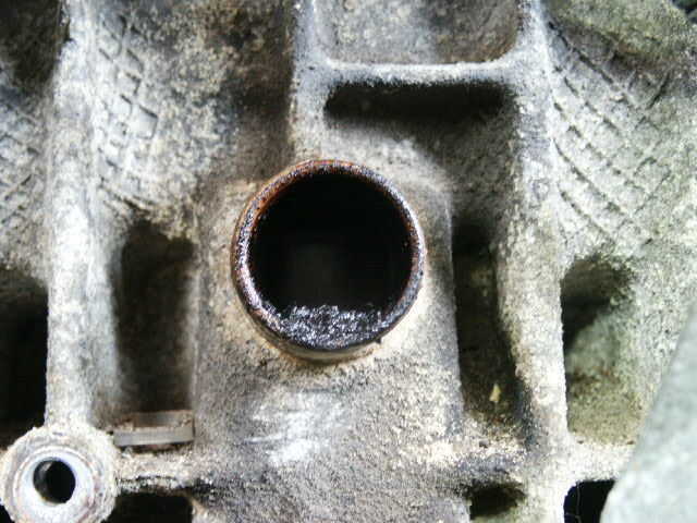
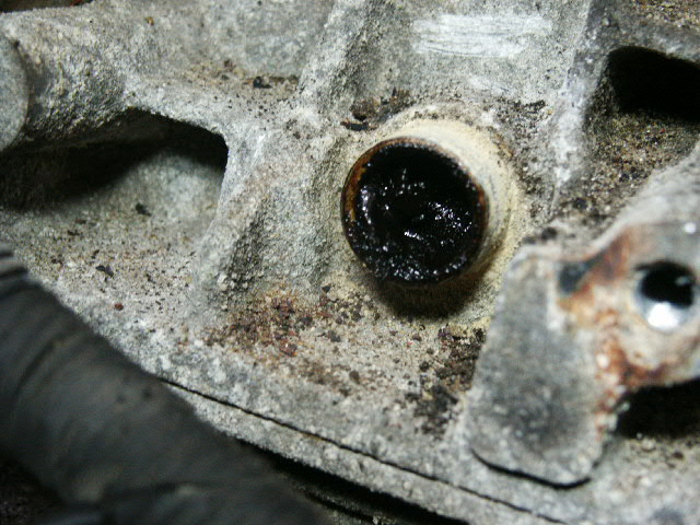
REPLACED THE PCV SYSTEM: The car has about 192,000 and the dipstick did NOT smoke but I think I had a slight leak at my RMS (had it replaced with the transmission). Well, a few of the guys encouraged me to do the PCV anyway. I don't think it was EVER done. My guess is that the PTC valve was NOT clogged, that's why the dipstick did NOT smoke. However, the lower hole in the block was almost totally clogged and the top hole had some gunk in it. I scraped it out with a long wood screw.
SERVICED THE EGR: A few days before I took the car to have the transmission done I was getting an EGR error. P0410 or something like that. Well, during the PCV system replacement I decided to paint the manifold (black ) so I pulled the manifold with the EGR attached. When I pulled the EGR off of the manifold to make sure the port to the intake was clean, it seemed ok, that is if that port was suppose to be a weep hole. Well, I stuck a tiny screw driver in it to make sure the hole went all the way to the throttle housing and the hole got a little bigger, then bigger, then bigger, it was almost totally clogged. A hole that started out as big as the hole on your cd drive (to eject it manually) and ended up being large enough to stick a pencil through it. WOW!
PAINTED THE MANIFOLD and FRONT SIDE OF THE MOTOR. Cleaned up the manifold and painted it along with the front half of the motor.
Top hole:
Bottom hole:
SERVICED THE EGR: A few days before I took the car to have the transmission done I was getting an EGR error. P0410 or something like that. Well, during the PCV system replacement I decided to paint the manifold (black
) so I pulled the manifold with the EGR attached. When I pulled the EGR off of the manifold to make sure the port to the intake was clean, it seemed ok, that is if that port was suppose to be a weep hole. Well, I stuck a tiny screw driver in it to make sure the hole went all the way to the throttle housing and the hole got a little bigger, then bigger, then bigger, it was almost totally clogged. A hole that started out as big as the hole on your cd drive (to eject it manually) and ended up being large enough to stick a pencil through it. WOW!PAINTED THE MANIFOLD and FRONT SIDE OF THE MOTOR. Cleaned up the manifold and painted it along with the front half of the motor.
Top hole:
Bottom hole:
#12
11-14-2011, 01:29 PM

Hello MHutchens, What are the specs torque of the tightness of the Intake manifold? Could you please share that?? Thanks in advanced, Patoygolf.. I will have to follow up on your directions. I have a 1994 Volvo 850 and I will be going to FCPGroton to order the items I will be needing just the way you have describe it.. I'm not sure although if I should go ahead and replace the Fuel injectors seal as well. I have well over 200k on this vehicle that I mentioned above. Also when you installed the oil separator does that have specs also when you reinstalled the new one??
#13
11-14-2011, 03:52 PM
Senior Member
Join Date: Feb 2009
Location: Glen Ellyn, IL
Posts: 564
Likes: 0
Received 0 Likes
on
0 Posts
#14
11-14-2011, 05:45 PM
I pulled my fuel rail off by accident. Took the seals and made sure they were clean and greased them. Didn't seem hard to me.
Last edited by rspi; 11-14-2011 at 05:47 PM. Reason: typo
#15
11-14-2011, 08:20 PM

Administrator
On a turbo engine it's important to have good seals on the bottom of the injectors as they can bleed off some of your boost if they are starting to get stiff and or cracked from age and heat. They can also leak vacuum or do both. The top will let you know as it'll leak fuel so there's no doubt it's time.
They usually aren't too difficult to do but it's easier if you do lube them up a bit first. I keep a tube of Vaseline in my tool box for helping all "O" ringed parts slip in a bit easier.
I use Vaseline because it doesn't effect or break down the rubber the way some other stuff can.
They usually aren't too difficult to do but it's easier if you do lube them up a bit first. I keep a tube of Vaseline in my tool box for helping all "O" ringed parts slip in a bit easier.
I use Vaseline because it doesn't effect or break down the rubber the way some other stuff can.
Last edited by Kiss4aFrog; 02-28-2013 at 01:25 PM.
#17
02-28-2013, 08:17 AM

rspi- I did the pcv service about a year ago (replaced oil seperator, hoses etc, didnt just clean them) I ordered the FCP Groton kit 95 850 NA. I left the fuel injectors alone. Cleaned out all of those ports. By ordering the kit I feel I bought a BUNCH of stuff I didnt need or use. Like they included 2 different intake manifold gaskets for example. If I were to do it again, I'd do it in warm weather when I could commute on the motorcycle, take stuff apart and order (maybe purchase locally?) only what I need. Exactly what I need. You know? No leftovers.
Oh and it still smokes from the dipstick like a beast....Dave
Oh and it still smokes from the dipstick like a beast....Dave
#18
02-28-2013, 08:02 PM
Hmmmm, well, the dip stick smoking deal is not the best test. Our S70 smoked for about 1,000 miles afterwards. My wagon did NOT smoke even when it was clogged. I really believe that the hose at the end of the manifold (on the passenger side) is what usually causes the smoking.
They double up parts because so many people have different parts swapped on to these old cars and if you order "only what you need", you may fall short. Better more than less. Heck, $145 every 5 years or 60,000 miles is not bad (unless you're driving 40,000 miles per year).
After doing about 7 of them, I'm down to about 2 hours for the job. Very surprised. My first 2 or 3 took 5 to 6 hours. When TECH told me he was doing them in 1-1/2 to 2-1/2 hours I was thinking about tossing my BS card down but after a few times it speeds up quite a bit. The slowest ones are the cars with EGR (that needs to be cleaned out) and TURBO (with the PTC needing cleaned). Those would likely still take 3 to 3-1/2 hours for me.
#19
03-01-2013, 09:28 AM
rspi- yeah thats what i figured with the extra stuff, just seems like maybe they are trying to cover too many bases. Maybe make 2 or 3 kits and drop the price 20 bucks? More part numbers to keep track of I know.
My 95 does have an egr but I dont think I cleaned it. wonder if that could be causing my smoking. (It's old enough to smoke you know! ha ha). Can I clean that from the top, inside the throttle body without taking all of that intake manifold stuff loose and digging in too deep?
I do a lot of repairs (almost all) myself, but the pcv job took me pretty long. I seem to remember having a rough time releasing the egr line. nuts were loose, connection wouldnt disconnect. worked on that for a long time. Dave
#20
03-01-2013, 09:59 AM
Yea, that darn EGR is a pain, kind of scary. When I had mine off the egr hole in the intake manifold was about the size of an ink pin tube, after cleaning it all out it was the size of a drinking straw. So it was at least 75% clogged. I was getting an occasional EGR code, gone after cleaning.
When I do them now, I don't even go under the car after those lower manifold bolts. My hands are small enough to reach them from up top but they do cramp me up a little.
When I do them now, I don't even go under the car after those lower manifold bolts. My hands are small enough to reach them from up top but they do cramp me up a little.