
Volvo DIM repair options (DIY)
#1
 05-28-2015, 09:46 AM


Join Date: May 2015
Location: DFW, Texsas
Posts: 48
Likes: 0
Received 0 Likes
on
0 Posts
DISCLAIMER:
I am not a mechanic, nor do I work in any kind of car shop. I am an electronics testing technician. I will not give any guarantees.
This guide is for if your DIM will turn off/on if you hit bumps, or the DIM itself. If your DIM turns off/on by itself this guide MIGHT work for you.
please refer to https://volvoforums.com/forum/volvo-...cluster-67209/ for information on how to remove the instrument cluster. (Some imaged in this thread have been used from that post)
#1 I have completed and works partially..
#2 I will edit from personal experience, the amount of money you spend on flux and a soldering iron is much better than sending it to a shop! (Please use a temperature controlled soldering iron, (250 C is an OK temp that I use personally to get past thermal conductivity, but lead-free solder melts at 220-240 C)
__________________________________________________ ___________
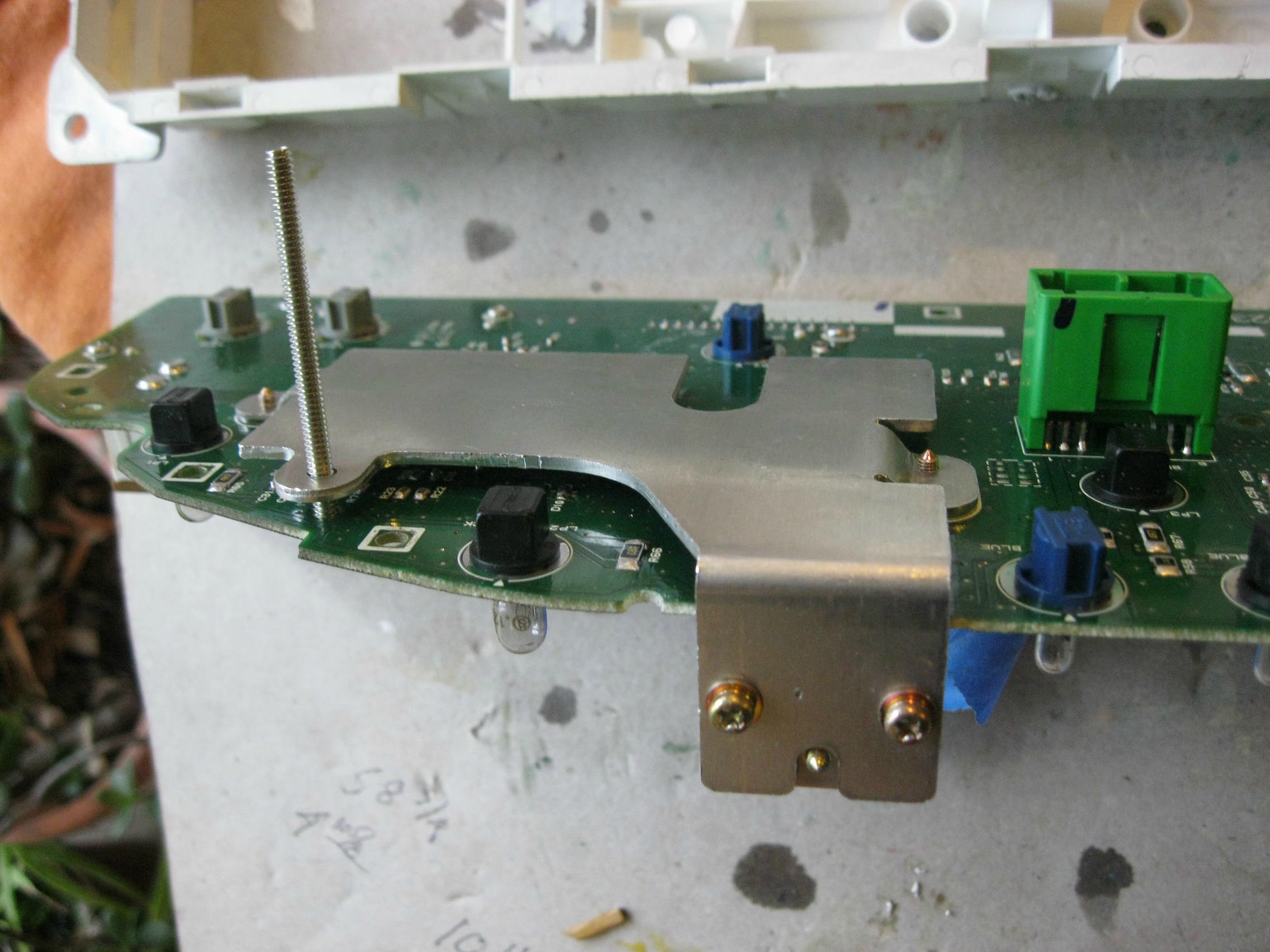
1) tension bolt on heat-sink
( Pretty self explanatory from pictures, I would have the DIM plugged in for this so you can find the tension that is right for you and will not allow the board to bend; I would personally suggest nuts and washers between the heat-sink and PCB as-well to keep the board from bending when the heat-sink is shaking from natural car vibrations, or button presses...)
What this does (from my experience) is that it bends the board to where something is able to make a proper electrical connection, Also I put the bolt in from the other direction. I have also put a nut and washer between the heatsink and board in order to keep it straight.
Whether it by the heat-sink to the ground plane (Heatsink is attatched to the ground pin of the voltage regulator; maybe for better power capability/lower resistance?)
Images of finished repair using this method.(From another user on the forum)
__________________________________________________ ____________
Advisory: I have tested over the weekend. Worked great but if you have a bad control arm that causes severe vibrations (such as in my case) it WILL break the solder joints you have just made.although it will stay on more of the time it is better to fix anything causing vibrations bad enough so shake the solder joints loose.
I personally did not get it going with just the motorola chip so I also hit all passive components and several other IC's. Best to hit anything that is affected with bend in the board.
2)Motorola reflow: (to add pictures around a week after posting)
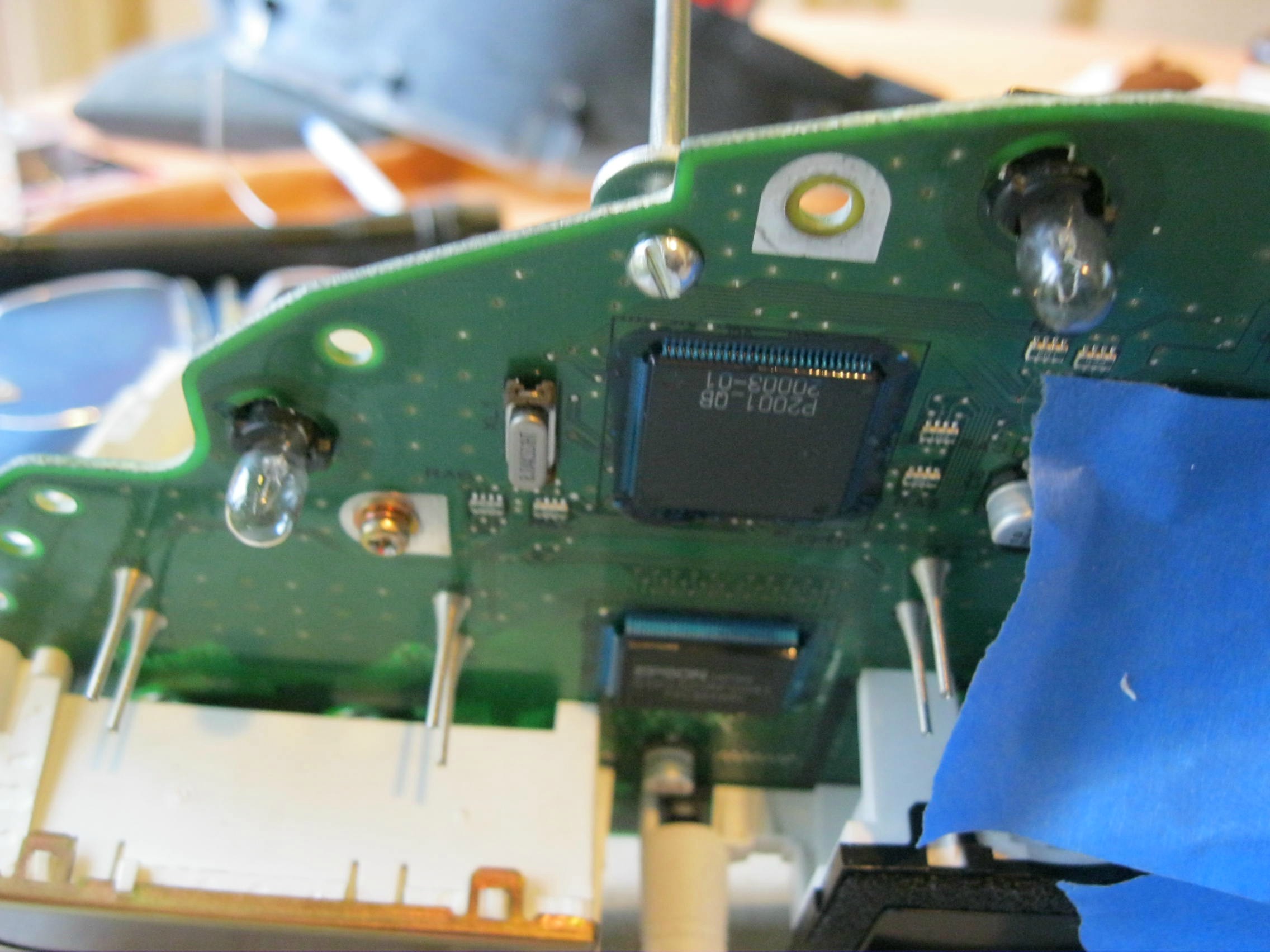
With the flex on the board you had to fix with the tension bolt it may have damages connections on the Motorola processor and may be still turning on/off at random, on bumps or you hitting the dashboard.
Now when you look at the Motorola processor you can see there is some blue gunk on it, I believe it is used to prevent and random bits of metal that may come in from shorting out the pins (probably the most expensive component of the whole board). That need to be removed. Now I would not suggest picking at it as you may damage the copper traces coming from the Motorola chip.
step 1: Use a cotton swab and some acetone or alcohol. (Can use acetone based nail polish remover) and remove the blue gunk covering the pins of the processor, remove excess acetone.
(alcohol works great, allow it to sit on top of the blue junk and then pick off as much as you can with a fingernail. then use a cotton swab, or another material)
I apologize for portrait filming...
step 2: put liquid no-clean flux on all the pins
(I say liquid and not paste as with my personal experience paste is messy and the board gets sticky. difficult to clean off, with liquid it is simple and easy, wont need much, easy to clean.)
step 3: using a soldering iron with a conicle tip touch each individual pin at or near the end. Allow flux to activate with heat then move to next pin.
(conicle tip: a cone shape tip that is usually default with a soldering iron, and not recommended by most but this will allow for head to transfer at a pace for people new with soldering small components not to damage them, and you will have more precision with it when hitting the pins)
step 4:
(optional depending on flux used, I have had flux be conductive before)
Using flux cleaner or alcohol clean off the flux residue on the board.
(Try to use a soft cloth such as from an old tshirt. clotton swabs, and other loose fabric may get caught on sharp points in the solder and be difficult to clean off.)
WARNING!: Flux cleaner WILL remove conformal coating. The conformal is used to protect against water/humidity, you can leave how it is without conformal coating but I would highly recommend going to fry's or look online for conformal coating if you are in a high humidity area.(alcohol might aswell, havent checked)
step 5:(Untested)
(Another optional item and can tackle in just about any way you want;
I would suggest do a few tests while driving to make sure it works the way you want it to before this step.)
Use silicone gunking on top of the pins to cover them so that they may not be shorted by foreign material.
You can use other types of gunking if you so wish. even cocking may work (Oh god I hope I spelled that right)
Just don't allow anything to go underneath the pins. Try to use a thick gunking that will not go under for easier repairs if needed later.
__________________________________________________ __________________________________________________ _______________-
If anybody has other repair options to share please post them below, and I will see about adding them to the list
I am not a mechanic, nor do I work in any kind of car shop. I am an electronics testing technician. I will not give any guarantees.
This guide is for if your DIM will turn off/on if you hit bumps, or the DIM itself. If your DIM turns off/on by itself this guide MIGHT work for you.
please refer to https://volvoforums.com/forum/volvo-...cluster-67209/ for information on how to remove the instrument cluster. (Some imaged in this thread have been used from that post)
#1 I have completed and works partially..
#2 I will edit from personal experience, the amount of money you spend on flux and a soldering iron is much better than sending it to a shop! (Please use a temperature controlled soldering iron, (250 C is an OK temp that I use personally to get past thermal conductivity, but lead-free solder melts at 220-240 C)
__________________________________________________ ___________
1) tension bolt on heat-sink
( Pretty self explanatory from pictures, I would have the DIM plugged in for this so you can find the tension that is right for you and will not allow the board to bend; I would personally suggest nuts and washers between the heat-sink and PCB as-well to keep the board from bending when the heat-sink is shaking from natural car vibrations, or button presses...)
What this does (from my experience) is that it bends the board to where something is able to make a proper electrical connection, Also I put the bolt in from the other direction. I have also put a nut and washer between the heatsink and board in order to keep it straight.
Whether it by the heat-sink to the ground plane (Heatsink is attatched to the ground pin of the voltage regulator; maybe for better power capability/lower resistance?)
Images of finished repair using this method.(From another user on the forum)
__________________________________________________ ____________
Advisory: I have tested over the weekend. Worked great but if you have a bad control arm that causes severe vibrations (such as in my case) it WILL break the solder joints you have just made.although it will stay on more of the time it is better to fix anything causing vibrations bad enough so shake the solder joints loose.
I personally did not get it going with just the motorola chip so I also hit all passive components and several other IC's. Best to hit anything that is affected with bend in the board.
2)Motorola reflow: (to add pictures around a week after posting)
With the flex on the board you had to fix with the tension bolt it may have damages connections on the Motorola processor and may be still turning on/off at random, on bumps or you hitting the dashboard.
Now when you look at the Motorola processor you can see there is some blue gunk on it, I believe it is used to prevent and random bits of metal that may come in from shorting out the pins (probably the most expensive component of the whole board). That need to be removed. Now I would not suggest picking at it as you may damage the copper traces coming from the Motorola chip.
step 1: Use a cotton swab and some acetone or alcohol. (Can use acetone based nail polish remover) and remove the blue gunk covering the pins of the processor, remove excess acetone.
(alcohol works great, allow it to sit on top of the blue junk and then pick off as much as you can with a fingernail. then use a cotton swab, or another material)
I apologize for portrait filming...
step 2: put liquid no-clean flux on all the pins
(I say liquid and not paste as with my personal experience paste is messy and the board gets sticky. difficult to clean off, with liquid it is simple and easy, wont need much, easy to clean.)
step 3: using a soldering iron with a conicle tip touch each individual pin at or near the end. Allow flux to activate with heat then move to next pin.
(conicle tip: a cone shape tip that is usually default with a soldering iron, and not recommended by most but this will allow for head to transfer at a pace for people new with soldering small components not to damage them, and you will have more precision with it when hitting the pins)
step 4:
(optional depending on flux used, I have had flux be conductive before)
Using flux cleaner or alcohol clean off the flux residue on the board.
(Try to use a soft cloth such as from an old tshirt. clotton swabs, and other loose fabric may get caught on sharp points in the solder and be difficult to clean off.)
WARNING!: Flux cleaner WILL remove conformal coating. The conformal is used to protect against water/humidity, you can leave how it is without conformal coating but I would highly recommend going to fry's or look online for conformal coating if you are in a high humidity area.(alcohol might aswell, havent checked)
step 5:(Untested)
(Another optional item and can tackle in just about any way you want;
I would suggest do a few tests while driving to make sure it works the way you want it to before this step.)
Use silicone gunking on top of the pins to cover them so that they may not be shorted by foreign material.
You can use other types of gunking if you so wish. even cocking may work (Oh god I hope I spelled that right)
Just don't allow anything to go underneath the pins. Try to use a thick gunking that will not go under for easier repairs if needed later.
__________________________________________________ __________________________________________________ _______________-
If anybody has other repair options to share please post them below, and I will see about adding them to the list
Last edited by zerorisers; 06-02-2015 at 09:35 AM. Reason: Added video for degunking
#2
11-16-2015, 08:08 PM

This guy is the best to do it. I have a 2003 Volvo V70 wagon and my cluster was completely dead. I took it to BBA REMAN and they weren't able to fix the problem. I called up my friend here and took the 2 hour drive and he fixed my car within a days turn around time. I was driving myself crazy thinking the problem couldn't get fixed and this guy saved the day. Do not waste your time going to the dealer or any other place. This $400 was well worth it and he's a very nice guy that's willing to work with you.
Check out Eastern Electronics in NJ!!!
He will see me again definitely. Thanks!
Check out Eastern Electronics in NJ!!!
He will see me again definitely. Thanks!
#3
12-31-2017, 01:46 PM

Member
Join Date: Apr 2009
Location: Ocala, FL
Posts: 53
Likes: 0
Received 0 Likes
on
0 Posts
I have an 04 V70R, there is not a heat sink on this unit. I did have the same issues however. After exploring the forums I felt confident that I could fix this problem....no gauges, no high beam indicator and all displays gone amuck.
Not removing the blue sealant, having a solder station that allows for precise soldering iron tip temperature of 350 degrees F and some patience and good troubling shooting practices is a must. With the board out of the unit and plugged in and sitting on a towel in the opening allowed me to use a plastic bone tool to poke around. Lightly bending the board, with car running, I was able to eliminate the left hand side of the PCB. Holding the PCB firmly and slightly tapping components caused the problems to come and go. Raking the pins on the SMD IC's I was able to diagnose it down to two of the IC's.
The OKI chip was where most of the problems originated from, top row of pins. As for the high beam indicator light, the Motorola chip in the upper right was where the cold solder joint was. Top row of pins.
By using a lens from a projection TV, I was able to place the iron tip directly on each pin. At 350, I only allowed for the tip to be on pin for about 2 seconds. I could see the solder run in that short amount of time. Surface mounted devices (SMD's) are great and are used a lot in automotive electronics because of their size. They are not the problem. The problem lies in the low or zero amount of lead in the solder used today. It appears that the lead is just soft and pliable enough to not break under road vibrations. Yes, I will most likely have other joints break loose, that's why I spent a few dollars for a good solder station. It has paid for itself several times over. Was in the neighborhood of $50 on Ebay.
If you're good with tools and have patience you can fix it yourself. I've been chasing this particular problem for a number of months now.
#4
03-25-2020, 08:42 AM

DISCLAIMER:
I am not a mechanic, nor do I work in any kind of car shop. I am an electronics testing technician. I will not give any guarantees.
This guide is for if your DIM will turn off/on if you hit bumps, or the DIM itself. If your DIM turns off/on by itself this guide MIGHT work for you.
please refer to https://volvoforums.com/forum/volvo-...cluster-67209/ for information on how to remove the instrument cluster. (Some imaged in this thread have been used from that post)
#1 I have completed and works partially..
#2 I will edit from personal experience, the amount of money you spend on flux and a soldering iron is much better than sending it to a shop! (Please use a temperature controlled soldering iron, (250 C is an OK temp that I use personally to get past thermal conductivity, but lead-free solder melts at 220-240 C)
__________________________________________________ ___________
1) tension bolt on heat-sink
( Pretty self explanatory from pictures, I would have the DIM plugged in for this so you can find the tension that is right for you and will not allow the board to bend; I would personally suggest nuts and washers between the heat-sink and PCB as-well to keep the board from bending when the heat-sink is shaking from natural car vibrations, or button presses...)
What this does (from my experience) is that it bends the board to where something is able to make a proper electrical connection, Also I put the bolt in from the other direction. I have also put a nut and washer between the heatsink and board in order to keep it straight.
Whether it by the heat-sink to the ground plane (Heatsink is attatched to the ground pin of the voltage regulator; maybe for better power capability/lower resistance?)
Images of finished repair using this method.(From another user on the forum)


__________________________________________________ ____________
Advisory: I have tested over the weekend. Worked great but if you have a bad control arm that causes severe vibrations (such as in my case) it WILL break the solder joints you have just made.although it will stay on more of the time it is better to fix anything causing vibrations bad enough so shake the solder joints loose.
I personally did not get it going with just the motorola chip so I also hit all passive components and several other IC's. Best to hit anything that is affected with bend in the board.
2)Motorola reflow: (to add pictures around a week after posting)
With the flex on the board you had to fix with the tension bolt it may have damages connections on the Motorola processor and may be still turning on/off at random, on bumps or you hitting the dashboard.
Now when you look at the Motorola processor you can see there is some blue gunk on it, I believe it is used to prevent and random bits of metal that may come in from shorting out the pins (probably the most expensive component of the whole board). That need to be removed. Now I would not suggest picking at it as you may damage the copper traces coming from the Motorola chip.
step 1: Use a cotton swab and some acetone or alcohol. (Can use acetone based nail polish remover) and remove the blue gunk covering the pins of the processor, remove excess acetone.
(alcohol works great, allow it to sit on top of the blue junk and then pick off as much as you can with a fingernail. then use a cotton swab, or another material)
I apologize for portrait filming...
Volvo 2002 s60 DIM degunking - YouTube
step 2: put liquid no-clean flux on all the pins
(I say liquid and not paste as with my personal experience paste is messy and the board gets sticky. difficult to clean off, with liquid it is simple and easy, wont need much, easy to clean.)
step 3: using a soldering iron with a conicle tip touch each individual pin at or near the end. Allow flux to activate with heat then move to next pin.
(conicle tip: a cone shape tip that is usually default with a soldering iron, and not recommended by most but this will allow for head to transfer at a pace for people new with soldering small components not to damage them, and you will have more precision with it when hitting the pins)
step 4:
(optional depending on flux used, I have had flux be conductive before)
Using flux cleaner or alcohol clean off the flux residue on the board.
(Try to use a soft cloth such as from an old tshirt. clotton swabs, and other loose fabric may get caught on sharp points in the solder and be difficult to clean off.)
WARNING!: Flux cleaner WILL remove conformal coating. The conformal is used to protect against water/humidity, you can leave how it is without conformal coating but I would highly recommend going to fry's or look online for conformal coating if you are in a high humidity area.(alcohol might aswell, havent checked)
step 5:(Untested)
(Another optional item and can tackle in just about any way you want;
I would suggest do a few tests while driving to make sure it works the way you want it to before this step.)
Use silicone gunking on top of the pins to cover them so that they may not be shorted by foreign material.
You can use other types of gunking if you so wish. even cocking may work (Oh god I hope I spelled that right)
Just don't allow anything to go underneath the pins. Try to use a thick gunking that will not go under for easier repairs if needed later.
__________________________________________________ __________________________________________________ _______________-
If anybody has other repair options to share please post them below, and I will see about adding them to the list
I am not a mechanic, nor do I work in any kind of car shop. I am an electronics testing technician. I will not give any guarantees.
This guide is for if your DIM will turn off/on if you hit bumps, or the DIM itself. If your DIM turns off/on by itself this guide MIGHT work for you.
please refer to https://volvoforums.com/forum/volvo-...cluster-67209/ for information on how to remove the instrument cluster. (Some imaged in this thread have been used from that post)
#1 I have completed and works partially..
#2 I will edit from personal experience, the amount of money you spend on flux and a soldering iron is much better than sending it to a shop! (Please use a temperature controlled soldering iron, (250 C is an OK temp that I use personally to get past thermal conductivity, but lead-free solder melts at 220-240 C)
__________________________________________________ ___________
1) tension bolt on heat-sink
( Pretty self explanatory from pictures, I would have the DIM plugged in for this so you can find the tension that is right for you and will not allow the board to bend; I would personally suggest nuts and washers between the heat-sink and PCB as-well to keep the board from bending when the heat-sink is shaking from natural car vibrations, or button presses...)
What this does (from my experience) is that it bends the board to where something is able to make a proper electrical connection, Also I put the bolt in from the other direction. I have also put a nut and washer between the heatsink and board in order to keep it straight.
Whether it by the heat-sink to the ground plane (Heatsink is attatched to the ground pin of the voltage regulator; maybe for better power capability/lower resistance?)
Images of finished repair using this method.(From another user on the forum)
__________________________________________________ ____________
Advisory: I have tested over the weekend. Worked great but if you have a bad control arm that causes severe vibrations (such as in my case) it WILL break the solder joints you have just made.although it will stay on more of the time it is better to fix anything causing vibrations bad enough so shake the solder joints loose.
I personally did not get it going with just the motorola chip so I also hit all passive components and several other IC's. Best to hit anything that is affected with bend in the board.
2)Motorola reflow: (to add pictures around a week after posting)
With the flex on the board you had to fix with the tension bolt it may have damages connections on the Motorola processor and may be still turning on/off at random, on bumps or you hitting the dashboard.
Now when you look at the Motorola processor you can see there is some blue gunk on it, I believe it is used to prevent and random bits of metal that may come in from shorting out the pins (probably the most expensive component of the whole board). That need to be removed. Now I would not suggest picking at it as you may damage the copper traces coming from the Motorola chip.
step 1: Use a cotton swab and some acetone or alcohol. (Can use acetone based nail polish remover) and remove the blue gunk covering the pins of the processor, remove excess acetone.
(alcohol works great, allow it to sit on top of the blue junk and then pick off as much as you can with a fingernail. then use a cotton swab, or another material)
I apologize for portrait filming...
Volvo 2002 s60 DIM degunking - YouTube
step 2: put liquid no-clean flux on all the pins
(I say liquid and not paste as with my personal experience paste is messy and the board gets sticky. difficult to clean off, with liquid it is simple and easy, wont need much, easy to clean.)
step 3: using a soldering iron with a conicle tip touch each individual pin at or near the end. Allow flux to activate with heat then move to next pin.
(conicle tip: a cone shape tip that is usually default with a soldering iron, and not recommended by most but this will allow for head to transfer at a pace for people new with soldering small components not to damage them, and you will have more precision with it when hitting the pins)
step 4:
(optional depending on flux used, I have had flux be conductive before)
Using flux cleaner or alcohol clean off the flux residue on the board.
(Try to use a soft cloth such as from an old tshirt. clotton swabs, and other loose fabric may get caught on sharp points in the solder and be difficult to clean off.)
WARNING!: Flux cleaner WILL remove conformal coating. The conformal is used to protect against water/humidity, you can leave how it is without conformal coating but I would highly recommend going to fry's or look online for conformal coating if you are in a high humidity area.(alcohol might aswell, havent checked)
step 5:(Untested)
(Another optional item and can tackle in just about any way you want;
I would suggest do a few tests while driving to make sure it works the way you want it to before this step.)
Use silicone gunking on top of the pins to cover them so that they may not be shorted by foreign material.
You can use other types of gunking if you so wish. even cocking may work (Oh god I hope I spelled that right)
Just don't allow anything to go underneath the pins. Try to use a thick gunking that will not go under for easier repairs if needed later.
__________________________________________________ __________________________________________________ _______________-
If anybody has other repair options to share please post them below, and I will see about adding them to the list
You could always use silicone based dielectric grease on those pins. Also, I think you meant to say �Caulking� as opposed to, well, you know. Lol🤣

Thread
Thread Starter
Forum
Replies
Last Post