K jet to LH 2.4 swap.. No spark?
#1
 08-04-2013, 08:21 PM


Join Date: May 2010
Location: Keystone State
Posts: 107
Likes: 0
Received 0 Likes
on
0 Posts
Hi,
My son and I are in the process of swapping over his 84 242 k jet system to LH 2.4 This has been a long struggle but so far it all seems to work but there is no spark when you crank it over. The fuel pumps turn on with the key and there is 12 v to pins one and four of the power stage wile cranking, and we have 12 v to the brand new coil. We are using the donor car (90 244) LH engine harness, ezk, ecu and maf. The donor engine and trans is from a 91 740 sedan. We've not connected the tach feed wire yet to the dash but the cps is plugged in..
What are we missing in the mix to cause spark? I've read somewhere about needing a Hall effect block mounted dizzy, but the 90 dizzy is in it now and it worked with that set up.. Lots of time was spent pouring over crappy diagrams and making posts to other sites with no constructive answers.. We are stumped, please help.
Cheers,
Mike and Mitch.
#2
08-04-2013, 09:13 PM

#3
08-04-2013, 09:36 PM
Join Date: May 2010
Location: Keystone State
Posts: 107
Likes: 0
Received 0 Likes
on
0 Posts
Hi pierce, thanks for the reply. No, we don't have the green book diagrams for either the recipient (84 242) or the 90 244 donor. Lots of time was spent tho, searching for the right/ clear diagrams. We can't figure out what is missing from the loop to signal the coil to spark .. Very frustrating.. The cps is what tells the coil to fire?
Thanks, m.
Thanks, m.
#4
08-04-2013, 10:03 PM
#5
08-05-2013, 01:54 AM


#6
08-05-2013, 02:04 AM
silly question, does your intake manifold have a cold start injector? if the 1991 740 didn't have one, you might want to use the ECU out of that 1991 740, as its likely got different software for no cold start injector (the later cars just enriched the mixture via the main injectors and did away with the cold start).
what version ECU is this? if you have the infamous -561 (bosch part number 0 280 000-561), that could be a problem, they were prone to failure.
what version ECU is this? if you have the infamous -561 (bosch part number 0 280 000-561), that could be a problem, they were prone to failure.
#7
08-05-2013, 02:22 AM

#8
08-05-2013, 02:08 PM

Hey Pierce,
We're using a turbo ECU and EZK from my old 740. The ECU is a 937 and I'll be using a goldbox EZK.
I have the 11-pin connector wired as follows to the 84' 242:
Both Red/Yellow wires coming from 11-pin connector are going to Fuse 5. (The thicker Red/Yellow is for fuel pump 12v output signal. The thinner Red/Yellow is for heated o2)
Both Red wires coming from 11-pin connector are going to Fuse 6. (These both appear to trace to the lh2.4 fuel pump relay)
Blue wire coming from 11-pin connector are going to switched 12v at Fuse 11.
I kept the stock 84' fuel pump relay in place and just wired the 11-pin wires to the fuse panel, which is making the lh2.4 fuel pump relay click and turns on the pumps.
The fuel pumps turn on with the key, but I have no spark. I have the blue wire coming out of the 2-pin connector by the coil running to switched 12v to power the coil. I can now hear the injectors firing and I have power to the ECU/EZK.
Thanks,
Mitch
#9
08-05-2013, 03:42 PM
the fuel pump relay is normally connected to the injection harness which also goes to the ECU right near to it. as shown in those diagrams above, its actually a dual relay on LH2.4 cars (and LH2.2, but not on kjet). one half of the relay switches the power to the ECU and injectors, while the other half of the relay is the power for the fuel pumps.
the fuel pump should only run about 1 second until the ECU detects engine movement.
I'm not sure which 11 pin connector you're talking about.
the fuel pump should only run about 1 second until the ECU detects engine movement.
I'm not sure which 11 pin connector you're talking about.
#10
08-05-2013, 07:16 PM
the fuel pump relay is normally connected to the injection harness which also goes to the ECU right near to it. as shown in those diagrams above, its actually a dual relay on LH2.4 cars (and LH2.2, but not on kjet). one half of the relay switches the power to the ECU and injectors, while the other half of the relay is the power for the fuel pumps.
the fuel pump should only run about 1 second until the ECU detects engine movement.
I'm not sure which 11 pin connector you're talking about.
the fuel pump should only run about 1 second until the ECU detects engine movement.
I'm not sure which 11 pin connector you're talking about.
ECU: 937 Turbo B230FT
EZK: 207 Gold Box
Factory: K-Jet goodness
Wiring as of now:
Thick Red/Yellow from 11-pin is going directly into the female spade terminal of the old Red/Yellow wires going into the K-Jet fuel pump relay. Fuel pumps are working as intended.
Thinner Red/Yellow from 11-pin connector is going to Fuse 5 (Heated o2)
Blue from 11-pin connector is going to Fuse 11 (switched 12v)
Both larger Red wires are going to Fuse 6 (I believe these are 12v constant for the ECU/EZK)
Blue wire from Coil is going to switched 12v. I have 12v at the coil with Key On and 10.5v while cranking.
We've tested for spark both directly from the coil wire and from plug #1.
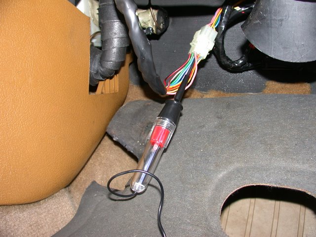
Here is a picture of the 11-pin connector I'm talking about. It is the one that is located directly next to the ECU/EZK and the fuel pump relay is also right there.
This isn't my 11-pin but this is just a reference picture.
Checked voltage at both the coil and at the power stage:
Coil
Key On - 12v
Cranking - 10.5v
Power Stage
Key On - 12v at pins 1 & 4
Cranking - 10.5v at pins 1 & 4
Coil is brand new and works in another car. The wires are also brand new.
Update for today:
I went out and tested the grounding on the ECU and EZK tonight.
There is a good ground at pin 17 of the ECU and at pin 14 of the EZK. These are the grounds that go on the intake under the bolts that hold down the fuel rail.
I also swapped to a known good working 92 940 Turbo EZK (also tried a working goldbox) and still, no dice. I also changed up my wiring for the fuel pumps. I have the large Red/Yellow coming out of the 11-pin now going directly into the K-Jet fuel pump Red/Yellow wires. Have fuel pumps prime with the key but still no spark.
This has to be something so simple.....
#11
08-05-2013, 09:19 PM
ah, THAT 11 pin connector, heh.
sadly, the 240 greenbooks don't detail the connectors the same way as the 900 books I've seen do.
I don't suppose the lh2.4 diagnostic box made its way under your hood? if it did, you could see if you get any 1-1-1 codes out of both the ECU (pin 2) and ICU (pin 6), which indicates that the processors in the respective CU's are alive. also, the ECU has a DTM3 which cycles the injectors, cold start valve, and some other stuff so you can verify operations.
have you confirmed the injectors are getting power when the key is on ? one pin of the connectors to the injectors (all 4 are wired in parallel) should be hot when ignition is on, the other pin gets switched to ground when the ECU says so.
#12
08-06-2013, 12:25 AM

I used this to bench test a junkyard motor last week (it's a 94 B230FT!!!! I'm excited). But it may help you. Basically at the bottom right are the connections I made to make to run off a car battery sitting on an engine stand. I have a green book on the ezk 116 system as well as an electronic copy of the green book for the LH2.4. if that doesn't help I can look through more specifics.
When I was testing my engine on the stand, everything seemed good but I got no spark or fuel. It turned out that my blue wire never got battery power. Since I used switches to simulate the key and the main relay I forgot to get power on the blue wire when my 'key' was on. The blue wire connects to pin 9 on the LH2.4 unit. It powers the MAF and some of the computer and the radio suppression relay. On the 94 LH2.4, the coil is also powered off the radio suppression relay. If you look at the bottom right the wiring diagram, you will see all the systems that I had to switch on battery power (except the battery connection directly to the radio suppression relay's contacts, just connect it directly).
Hope that helps.
#13
08-06-2013, 12:41 AM
#14
08-06-2013, 06:44 PM
Harness: 90' Volvo 240
#15
08-06-2013, 08:19 PM
Update for today:
Went out and probed all the fuses I'm using both with key on and while cranking. Fuse is good to the fuel pumps.
Fuse 5 - Factory fuel pump fuse
Key on: 12v
Cranking: 10.5v
Fuse 6 - Factory ECU location that I have both of my large red wires coming from 11-pin connector going to.
Key on: 12v
Cranking: 10.5v
I also hooked up the blue wire from the 11-pin to a battery box.
Cranking: 12.02v
I pulled out the coil wire and stuffed a screwdriver in the end to check for spark, and noticed that when I touch the blue wire from the 11-pin to 12v there is a light crack and spark from the coil wire to the strut nut that I'm using for ground. It also gives off a faint spark when I remove the 12v from the blue wire. WTF?
Also, hooked up a noid light to injector #1 and it's not firing.
Used the diagnostic port #2 and the flash code was 1-1-1
In diagnostic port #6 for ignition I had a weird occurrence. When the lights would blink rapidly the first time for the injectors, it was silent, but when it would try to test the IAC, is sounds like the injectors are firing during the IAC test. (I'm not running an IAC) I think it goes in the order of fuel injector test, then the IAC test?
-Mitch
#16
08-06-2013, 08:42 PM
note that most 240's do NOT use fuse 6 for the ECU and injection, only the last couple years... instead all the rest had an inline fuse on a wire from the battery which went to the harness and back to the ECU...
but, it sounds like your ICU isn't working right. on my wiring diagrams, the ICU and the coil gets its power from the ignition switch in either position II (run) or III (start).
but, it sounds like your ICU isn't working right. on my wiring diagrams, the ICU and the coil gets its power from the ignition switch in either position II (run) or III (start).
#17
08-08-2013, 11:36 PM
It also gives off a faint spark when I remove the 12v from the blue wire. WTF?
I'm not convinced that the computer is dead.
So go here: http://volvowiringdiagrams.com/volvo...20Complete.pdf
Go through the troubleshooting procedure. The electric system troubleshooting starts on page 38, but I suggest familiarizing yourself with the whole manual. Page 24 starts a section about using the diagnostic system. This is written for a 240, but it helped me find my problem with my 940 engine real quick. I have one for the ignition system too for my 740, but it's not in PDF form, so if you can't find it there, I may see about scanning it in.
Last edited by Titan Joe; 08-08-2013 at 11:51 PM.
#18
08-09-2013, 12:14 AM
So go here: http://volvowiringdiagrams.com/volvo...20Complete.pdf
Go through the troubleshooting procedure. The electric system troubleshooting starts on page 38, but I suggest familiarizing yourself with the whole manual. Page 24 starts a section about using the diagnostic system. This is written for a 240, but it helped me find my problem with my 940 engine real quick. I have one for the ignition system too for my 740, but it's not in PDF form, so if you can't find it there, I may see about scanning it in.
Go through the troubleshooting procedure. The electric system troubleshooting starts on page 38, but I suggest familiarizing yourself with the whole manual. Page 24 starts a section about using the diagnostic system. This is written for a 240, but it helped me find my problem with my 940 engine real quick. I have one for the ignition system too for my 740, but it's not in PDF form, so if you can't find it there, I may see about scanning it in.
Engine Tune and Performance is written by guys who've analyzed the problems that have developed over 20+ years of real world. it has invaluable troubleshooting tips for various scenarios.
#19
08-09-2013, 03:13 PM
#20
08-09-2013, 03:52 PM
no spark is your fundamental problem?
lets see... I do believe I'd get a 12V LED test light, and check to ensure there's power at the coil pin 15 (blue wires) when the ignition is on. now hook the test light to coil pin 1 (red/white wires?) and crank the car, the light should blink. one red-white wire goes to the power module pin 1, the other goes to the tach in the dashboard (if you have one, otherwise should be unconnected and insulated).
if thats blinking, then your coil should be making spark. time to look at the distributor and/or coil-to-distributor HV wires.
ensure you have power at Power Module pin 4 (should be wired to a blue wire to coil pin 15), and ground on power module pin 2 (black), which should be grounded together with the ICU pin 20 (brown-black) on the 'logic' side of the intake manifold grounds.
If the power and ground stuff is AOK, then see if you get blink-blink on pin 5 (grey wire inside shield, shield is connected to pin 3) when you crank the car over.
if you see pulses on power module pin 5 but not on pin 1 or coil pin 1, then the power module is fried.
If you're not seeing those pulses, power module pin 5 comes from the ICU pin 16.
ensure the ICU gets power on pin 5 (red wire) all the time (this is from an inline fuse direct off the battery on a 1990 [same inline fuse on the left fender well that powers the ECU and injection system], and fuse 6 on a 1991+). the ICU gets power on pin 6 (blue wire) when the ignition is on.
the crank position sensor has 2 wires and a grounded shield to the ICU. CPS pin 3 goes to the black wire and grounded shield and to ICU pin 11. CPS pin 1 goes to blue-yellow to ICU pin 10, and CPS pin 2 goes to red-yellow to ICU pin 23. these last two are a low level differential signal, and unless you have an oscilloscope, its probably impossible to read this.
ICU pin 17 is an amplified/cleaned up (logic level) version of this CPS signal that goes on a brown wire to ECU pin 1, indicating RPM, this is critical to vehicle operation. you should see pulses on this signal when the vehicle is cranking over. if you don't, then either the ICU or the CPS is the root problem.