
crank sensor, same as rpm sensor?? help?


Thread Starter
|
Junior Member
Joined: Dec 2011
Posts: 7
Likes: 0
For almost 2 months ago now, i fixed my rpm sensor because i got faultcode : 1-3-1: Ignition system RPM signal missing
Now i got : 2-1-4: Crankshaft position/speed sensor faulty.
Dont tell me that this is the same sensor?
Got a volvo 740, 89mod, b230f engine.
thanks for any help
Now i got : 2-1-4: Crankshaft position/speed sensor faulty.
Dont tell me that this is the same sensor?
Got a volvo 740, 89mod, b230f engine.
thanks for any help

Senior Member
Joined: Jan 2011
Posts: 1,210
Likes: 14
From: New York
For almost 2 months ago now, i fixed my rpm sensor because i got faultcode : 1-3-1: Ignition system RPM signal missing
Now i got : 2-1-4: Crankshaft position/speed sensor faulty.
Dont tell me that this is the same sensor?
Got a volvo 740, 89mod, b230f engine.
thanks for any help
Now i got : 2-1-4: Crankshaft position/speed sensor faulty.
Dont tell me that this is the same sensor?
Got a volvo 740, 89mod, b230f engine.
thanks for any help
Thread Starter
|
Junior Member
Joined: Dec 2011
Posts: 7
Likes: 0

Thread Starter
|
Junior Member
Joined: Dec 2011
Posts: 7
Likes: 0


So some of you gotta be wrong here, because 2 months ago i got fault code 1-3-1 (rpm sensor, wich Swiftjustice helped me with in my other post) and now i got 2-1-4 (wich im not sure anymore what is any more)
Here is the link for the other post: https://volvoforums.com/forum/volvo-...36/#post299994

Super Moderator
Joined: Aug 2008
Posts: 2,580
Likes: 9
From: Dallas, TX
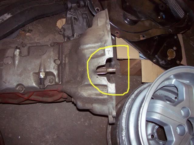
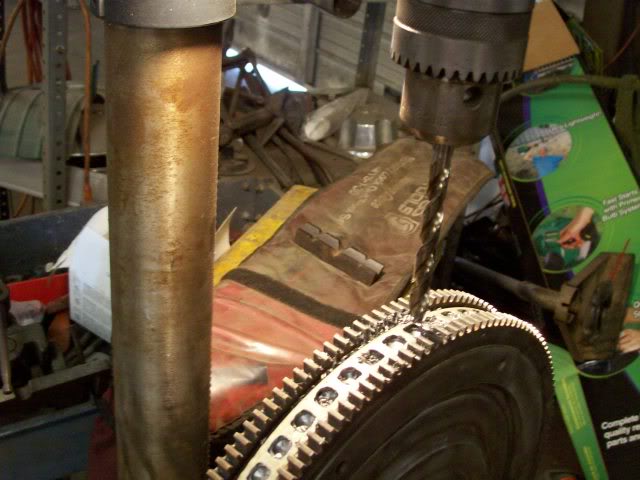
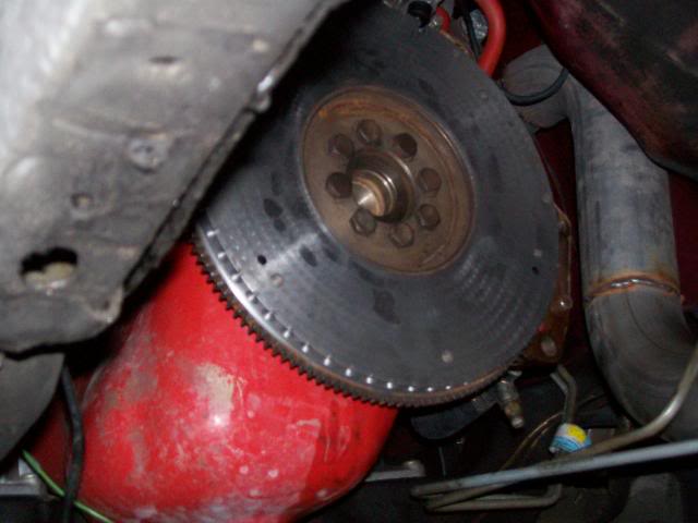
Yup, the pictures are the same. 214 is an erratic rpm signal. Most often, this is because the sensor is either loose and wiggling around, or the bracket that the sensor mounts to is just too tall. Occasionally, I've had to grind the pot metal bracket down a bit to get the entire assembly closer to the flexplate/flywheel dimples. I've had a bit of experience with this as I converted a flat, pre 87 flywheel without dimples to dimples to work on my 89 245...I did it by using a flexplate from an auto car and using it as a template to drill the dimples...
Senior Member
Joined: Jan 2011
Posts: 1,210
Likes: 14
From: New York
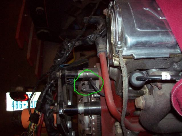
The 2-1-4 code is for the regina system which you don't have. The RPM sensor is what swift has in his pictures. I thought you were referring to the speed sensor which is the feed to the speedometer and ECU. It still sounds like you have a problem with the rpm sensor as shown in the pictures. I would clean the connector and check to see if it is functioning.
Super Moderator
Joined: Aug 2008
Posts: 2,580
Likes: 9
From: Dallas, TX
JT, I'd have to disagree that the code is specific to Reginas...I fought this code with my 245 when I used the converted flywheel. The diameter of the flywheel is .5 inches less than called for and the crank sensor was too far from the wheel. I had to grind down the top side of the sensor holder 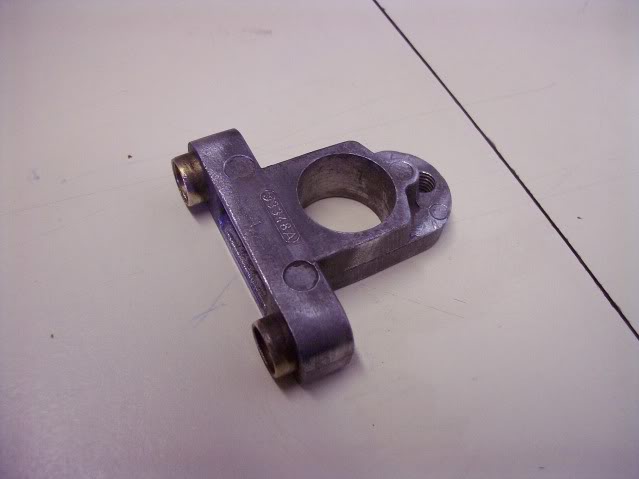 so the sensor would sit deeper and thus closer to the flywheel. It took me a couple of tries to get rid of the code.
Regardless, either the holder, sensor or connector is most likely loose.
so the sensor would sit deeper and thus closer to the flywheel. It took me a couple of tries to get rid of the code.Regardless, either the holder, sensor or connector is most likely loose.
Thread Starter
|
Junior Member
Joined: Dec 2011
Posts: 7
Likes: 0
ok, im not following you guys 100% here. But i i'll try to ask a other way.
131 is the rpm sensor and 214 is the crank sensor, i cant find any answers that tells me the difference?
Does any body know the symptoms for fault code 2-1-4?? Because my volvo loose all power around 2000-3000 rpm?? Is 2-1-4 the reason for this?
131 is the rpm sensor and 214 is the crank sensor, i cant find any answers that tells me the difference?
Does any body know the symptoms for fault code 2-1-4?? Because my volvo loose all power around 2000-3000 rpm?? Is 2-1-4 the reason for this?
Super Moderator
Joined: Aug 2008
Posts: 2,580
Likes: 9
From: Dallas, TX
131 is the ignition system rpm signal, i.e. the ICU which can and will pull timing is not receiving a signal...generally because of either a bad sensor or bad connection. 214 is an erratic signal being received. For me, that meant the sensor was just a bit too far from the dimples it reads. Check the pig tail on the sensor...look closely at the pins in both sides of the connector. Look for bent or corroded pins. If nothing, then make certain the 10mm bolt holding it to the bracket is tight. If it is tight, then see if the two bolts holding the bracket to the block are tight. Other options are that it could be a bad connection at the ecu or, less likely, the icu. You may very well need to drag out a digital volt meter and start checking at the ecu if it isn't a simple connection issue. Also...even though a crank sensor is a simple item, it is not unusual for new and like new parts to fail these days, given the lack of quality of the usual manufacturing country.

Junior Member
Joined: May 2014
Posts: 4
Likes: 0
So I have a volvo 740 GLE 1986, not sure of the motor, the sticker is missing. I tried to find the Crankshaft Sensor on top of the Bell housing below the distributor cap but I cannot find the RPM sensor. I am trying to locate it because it was malfunctioning for a while and then stopped working completely, I tried putting a new cluster in and it still didn't react, so now I suspect the sensor. Any idea where else this thing could be located?

no mo volvo
Joined: Oct 2010
Posts: 11,289
Likes: 109
From: 37 North on the left coast
ok, cluster... so you're saying your tachometer isn't working?
the tachometer is connected to the ignition power module pin 1 which also goes to pin 1 on the coil via a red-white wire... unless you have a 'rex' ignition system, then its connected to pin C of the left connector to the power/module/coil hybrid, allso via a red/white wire.
the tachometer is connected to the ignition power module pin 1 which also goes to pin 1 on the coil via a red-white wire... unless you have a 'rex' ignition system, then its connected to pin C of the left connector to the power/module/coil hybrid, allso via a red/white wire.
Junior Member
Joined: May 2014
Posts: 4
Likes: 0
Yes, the tachometer is what I was trying to describe. The engine is a B230F. I checked the ignition coil and it only has 2 white and 1 blue wire coming out. THANK YOU PIERCE for helping me figure this out. It looks like I have to remove the distributor cap, pull of the rotor and on and on. Anyone know good volvo mechanic who knows old volvos in Long Island, NY?
http://i123.photobucket.com/albums/o...03973913_o.jpg
http://i123.photobucket.com/albums/o...03973913_o.jpg
Last edited by hlcynik; Sep 18, 2014 at 08:49 PM.
no mo volvo
Joined: Oct 2010
Posts: 11,289
Likes: 109
From: 37 North on the left coast
at the coil, pin 15 should only have 1 blue wire, thats power from the ignition switch.
coil pin 1 can have one or more white wires with thin red stripes. these go to the ICU (Bosch ignition control unit), the tachometer. and, maybe the fuel pump relay/control... but these mutliple things canb e sliced somewhere other than at the coil.
check that 2nd white wire carefully, does it have a faded red stripe? if so, move it to the other side of the coil, and see if that doesn't fix your tach.
Junior Member
Joined: May 2014
Posts: 4
Likes: 0
The thing is I looked under the distribution cap with a flashlight and found where the impulse sensor plug protrudes and it is clearly hanging loose, which it shouldn't. So that explains why it would work and then stop in the beginning. I did look for a faded red strip on the white wires and didn't find any, there is another wire with a faded red strip but that doesn't connect to the ignition coil and goes entirely else where.
no mo volvo
Joined: Oct 2010
Posts: 11,289
Likes: 109
From: 37 North on the left coast
the blue wire to the coil is ignition switched power. the white-red wire is the timing pulses from the ICU, and this s what the tach watches (although the actual wire to the ach might come from closer to the ICU).
afaik, white-with-red-stripe is ONLY used on ignition timing, its otherwise very uncommon-to-non-existant.
so.... figure out where that white wire thats plugged into the blue side of the coil is going.... there shouldn't be anything there, but maybe some hack before you put a accessory on there as a easy-to-find source of ignition power? to which I'd say, ugh, but whatever.
Junior Member
Joined: May 2014
Posts: 4
Likes: 0
So after some investigation and a little research I figured out that the hall sensor in the Distributor was broken. So I purchased a new cap, rotor, distributor and seals and put it in. Even though the installation was successful the RPM gauge did NOT start working. I guess maybe it is the gauge itself. Special thanks to Pierce who helped me narrow things down. In the end the parts needed replacing, for example a cap and rotor are replaced as maintenance every 50,000 miles.
Here is the video on youtube in-case someone has to do something similar.
Here is the video on youtube in-case someone has to do something similar.
no mo volvo
Joined: Oct 2010
Posts: 11,289
Likes: 109
From: 37 North on the left coast
if you can find the wire you think goes to the tach, switch ignition on, and repeatedly tap it as fast as you can on a 'hot' signal, the tach needle should jump. that wire should be connected to the coil pin 1

Junior Member
Joined: Oct 2022
Posts: 27
Likes: 1
Yup, the pictures are the same. 214 is an erratic rpm signal. Most often, this is because the sensor is either loose and wiggling around, or the bracket that the sensor mounts to is just too tall. Occasionally, I've had to grind the pot metal bracket down a bit to get the entire assembly closer to the flexplate/flywheel dimples. I've had a bit of experience with this as I converted a flat, pre 87 flywheel without dimples to dimples to work on my 89 245...I did it by using a flexplate from an auto car and using it as a template to drill the dimples...
Attachment 18379
Attachment 18380
Attachment 18379
Attachment 18380
I sort of hacked my way into this older thread because it relates to an issue I'm having..
I'm fighting a no start issue with my 89 240
the starter gear broke into bits and it got carried up bent the disk up a bit and rubbed out the sensor.
I don't know if its not getting pulses. it starts and runs about a revolution and quits. maybe I can get a scope on this wire and see a trace? I have a scope. can I splice into a wire at the ECU connector maybe?
I thought you might know what that gap "should be' . I might try grinding down that piece if I can remove it can always add shims..
I might have more than one bad sensor, one is a cheapo.. its possible. what should the resistance through the sensor be? I think I can measure an output by wagging a screwdriver in front of the sensor with a meter connected. I might try that.
I did have it running perfectly after messing with all this stuff , but she went a mile and that amounted to a tow home again.
maybe problems with that powerstage amp , I'm more than a bit confused.
I drilled about a 1" hole in the bellhousing down near the inspection covers that pop out to help access. I got it pretty well straight. Id say within .020 or so.. does it have to be perfect? I'm trying to avoid pulling the tranny. with my luck it will be some other thing and that's a huge job for me, without a warm dry shop.
I stuck a depth gauge down where the sensor goes so I can compare that to the amount that the sensor protrudes and the difference will be the gap. I don't know what gap I'm shooting for. Thought you might know.
Thanks !
Phil