
Radio Suppression Relay


Senior Member
Joined: Jun 2009
Posts: 748
Likes: 1
From: Utah (for now)
It supplies the power to the injectors. Since the injectors are switching on and off all the time the power flow is stop and go. This is a form of AC power. It's only in one direction but it pulses. That causes electromagnetic induction and is the same idea behind how a radio antenna works. So it causes some electromagnetic interference. By putting it out under the hood they reduce the amount of interference that can be picked up by the radio in the dash. 240's don't even have them.

no mo volvo
Joined: Oct 2010
Posts: 11,289
Likes: 109
From: 37 North on the left coast
to be more specific...
on the 240, the injectors were powered by the main fuel injection relay, which was behind the glovebox, several feet from the radio.
on the 740, they moved all the relays to a central relay panel directly under the radio, ooops! so to fix the awful static (mostly on AM), they added the radio suppression relay under the hood, which is turned on by the main fuel injection relay, and supplies power to the injectors and on some years, the coil.
on the last year or two of non-turbo 940's, they flipped it around, and used the radio suppression relay under the hood as the MAIN fuel injection relay, and powered the ECU off it too. on these cars, the fuel pumps were controlled by a separate simple relay, while on all the previous cars, the fuel pumps were controlled by a 2nd relay inside the same fuel injection main relay.

Junior Member
Joined: Apr 2014
Posts: 22
Likes: 0
to be more specific...
on the 240, the injectors were powered by the main fuel injection relay, which was behind the glovebox, several feet from the radio.
on the 740, they moved all the relays to a central relay panel directly under the radio, ooops! so to fix the awful static (mostly on AM), they added the radio suppression relay under the hood, which is turned on by the main fuel injection relay, and supplies power to the injectors and on some years, the coil.
on the last year or two of non-turbo 940's, they flipped it around, and used the radio suppression relay under the hood as the MAIN fuel injection relay, and powered the ECU off it too. on these cars, the fuel pumps were controlled by a separate simple relay, while on all the previous cars, the fuel pumps were controlled by a 2nd relay inside the same fuel injection main relay.
on the 240, the injectors were powered by the main fuel injection relay, which was behind the glovebox, several feet from the radio.
on the 740, they moved all the relays to a central relay panel directly under the radio, ooops! so to fix the awful static (mostly on AM), they added the radio suppression relay under the hood, which is turned on by the main fuel injection relay, and supplies power to the injectors and on some years, the coil.
on the last year or two of non-turbo 940's, they flipped it around, and used the radio suppression relay under the hood as the MAIN fuel injection relay, and powered the ECU off it too. on these cars, the fuel pumps were controlled by a separate simple relay, while on all the previous cars, the fuel pumps were controlled by a 2nd relay inside the same fuel injection main relay.
I�ve been trying to track down an intermittent electrical fault on a 1990 740 for about a week now and it�s not getting better. It�s got the two ECU�s � one for spark and one for fuel (beautiful � NOT). I�ve been nursing the car along with a push-button I put in the dash to activate the cold start fuel injector, but the regular fuel has just about cut out. The scope shows a sort of half-baked pulse on the injectors, but they�re not delivering fuel.
Fuel pressure is OK and I�ve even swapped the whole injector stack from a working 740 � no change. I�ve been trying to trace pin 18 from the fuel ECU � which on the wiring diagram is shown to go straight to the injectors. There is like about 580 ohms between pin 18 on the ECU socket and the grey wire on the injectors (wired in parallel) � that should read about 0 ohms according to the wiring diagram.
The injectors are not individually wired to ballast resistors as shown in the wiring diagram because the injector plugs all have 0 ohm between the individual grey and green wires respectively. That makes me think I�m looking at the wrong wiring diagram. I�ve traced the ECU cable through two harness plugs & sockets to what I thought was the ballast resistor next to the intake filter box. But it seems it�s an ignition control unit (Bosch 0 227 100 124). The thing is while blue (pin 4) goes to the ignition coil, pin 5 on this unit (grey wire) reads 0 ohm to the grey wire on the injector stack, only when the ignition is on � presumably the radio suppression and fuel relays need to be on. I can�t see why there should be a link between the ignition control and the fuel control � that�s also not shown on the wiring diagram.
I just realised that a lot of these connectors have some brown sort of wax that gets in the way when you push them back together and makes the leads and contacts come out � maybe I�ll just solder them back together and throw the plugs away.
My query to you is: if I decide to bypass all the potential problem stuff like radio suppression relays etc. and connect pin 18 of the ECU straight to the injectors and connect the other terminal of the injectors to B+, will it blow up the ECU? (I�m hoping pin 18 is actually what it says on the wiring diagram � but who knows?). The injector resistance (total) is about 4 ohm which would put a load of around 3 amps on pin 18 of the ECU, which is fused with 15A for the whole unit. I also have not been able to find out what any ballast resistors should be � why resistors should be individually wired to each injector as shown on the wiring diagram is beyond me � another piece of Bosch brilliance no doubt. There is of course no circuit diagram available for the actual ECU � that would be telling. It would also let me know what type of output transistor or FET or whatever and the specs. Anyway I guess I could use a 2955 or something (15A PNP transistor) just to make sure. Would that blow up the injectors though (about 9W on each coil?)
Thanks � I realise your post is about 6 years old, but maybe as a super moderator you�re still on line occasionally.
no mo volvo
Joined: Oct 2010
Posts: 11,289
Likes: 109
From: 37 North on the left coast
ballast resistors are only used on turbos, and there's 2 resistors for the 4 injectors.
that bosch module is the 'power module', not the ignition control unit. think of it as a power amplifier, it switches the coil pin 1 to ground on demand, the output of the ignition control unit (under the dashboard) goes to the input of this power module.... there shouldn't be any connections between the ignition power module and the fuel injection system...
bypassing the radio suppression relay and connecting the injectors directly to the battery will likely cause the battery to drain.
I don't have the wiring diagrams directly in front of me right now, but the output of the fuel injection computer (ECU) works like a switch to ground.... in electronics we call that an 'open collector'... the current path is battery+ -> radio suppression relay -> injector -> ground.
turbos use a different higher volume injector, which is ''lower impedance" (less resistance) so it needs the ballast resistors to limit the current.
good god, I wouldn't go around hacking out connectors and soldering up the harness, or you'll end up with a complete mess that noone can sort out. with the ignition switched on, one side of the injectors should be seeing a solid 12V. when the ECU grounds its output to them, the other side should go to 0 V and all 4 injectors should spray for the duration of that pulse. its that simple.
the cold start injector is on a different output. later ECU's did away with it entirely, and just pulse the main injectors longer when starting a cold engine.
Junior Member
Joined: Apr 2014
Posts: 22
Likes: 0
Well contrary to all expectations she�s back on the road! The wiring diagram is irrelevant, of course, and bears no resemblance to the real thing in any shape or form. Pin 18 on ECU fuel injector drive? Forget it � that pin has NO pulse on it. So I put the scope back on the half-baked injector pulse � this time with one channel on the green wire and one on the brown with the shield grounded to chassis. Before I did that I got so frustrated with everything that I lifted the fuel rail to check an injector � just one - and found that they give a nice constant spray with the input voltage down to as low as 5V (cut the wire on the plug and jury-rigged it to the battery with about 30 ohm in series with the injector). But there was no fuel going through the injectors when the scope showed a differential of about 5V, so that�s not quite a high enough voltage to run them at a pulse speed of 10Hz.
So I checked what the two traces were doing (brown and green wires on injectors) and found that the brown had a good solid downward signal from supply (12V) to about ground, but the green followed this about half way instead of remaining steady. Maybe you could tell me what could cause that? The radio interference relay maybe? Anyway I thought I�d stabilise the green a bit by putting in a 10 ohm resistor to B+ and what do you know � she ran beautifully! Still needs checking out on the scope and maybe adjust resistor or just run it to B+ (ignition-switched, of course), but it�s a start.
So what can make the green wire wonky? A relay? You�d know more about that than me, that�s for sure! Anyway I�m just glad there�s some hope after all.
Cheers, Jackie
Junior Member
Joined: Apr 2014
Posts: 22
Likes: 0
Hey - just saw your nice reply - didn't expect anything so soon- and yeah, thanks, it clears up a few things. Especially the bit about one of the injector wires seeing a good solid 12V. That explains what I found with putting a resitor on that wire (see my subsequent post).
You're right about the harness - I did contemplate soldering it all up but I could see a nightmare coming and gave it away as a bad idea!
Cheers
You're right about the harness - I did contemplate soldering it all up but I could see a nightmare coming and gave it away as a bad idea!
Cheers
no mo volvo
Joined: Oct 2010
Posts: 11,289
Likes: 109
From: 37 North on the left coast
if you're you're testing pin 18 when its still connected to the injectors, you should see 12V to near 0V back to 12V as it pulses when the engine is cranking over. you can't see these pulses with a volt meter, they are too fast... you need an oscilloscope to really see them. they make a thing called a 'noid light' that you plug between the cable and the injectors, they blink when the injectors fire.
Junior Member
Joined: Apr 2014
Posts: 22
Likes: 0
The only wiring diagram I could find for 1990 740�s lists ECU wiring for Regina, LH-Jetronic 8 valve, LH-Jetronic 16 valve, and LH-Jetronic turbo. Only LH-Jetronic turbo shows 2 ECU�s. I don�t think my car is a turbo (what�s a turbo?) but I actually did put the scope on pin 18 and the trace was flat (+/- 1mV) so that makes me think it�s the wrong diagram. I�ve finally located the radio interference suppression relay (Volvo 899931 1323592-1, 12V 40A) stuck to the water reservoir bracket on the right front, whoopee! Now I can dismantle it and fix the �non-serviceable parts� to make it go, when I get time. At the moment the jury-rigged fuel injectors are purring like a cat! Have you ever heard anything more ridiculous? I guess it�s what makes the outback tick.
no mo volvo
Joined: Oct 2010
Posts: 11,289
Likes: 109
From: 37 North on the left coast
*ALL* those systems have 1 ECU (Fuel Injection Control Unit) and one ICU (Ignition Control Unit). the Bosch systems (LH) have an additional ignition 'power module', whereas the Regina 'square' coil has the power module built into the coil.
I have no idea what all you're talking about dual vs single ECU.
anyways, I have the diagrams for 1991 740/940, I don't think 1990 are significantly different.
The Bosch LH 2.4 injection cars use Bosch EZ 116K ignition, this was used on regular as well as turbos.
The Regina injection cars use Rex-I ignition.
I'm going to post the FI and Ignition systems of 3 combinations, B230F w/ Bosch, B230FT (turbo) with Bosch, and B230F with Regina/Rex. I didn't capture the 16V pages.


no mo volvo
Joined: Oct 2010
Posts: 11,289
Likes: 109
From: 37 North on the left coast
On all 740/940's, the ECU is located on the right side of the right front foot well, just forward of the lower door hinge, behind the plastic kick panel.
On all 740/940's, the ICU is located behind the dashboard on the firewall near the pedal assembly. AFAIK, on RHD cars, it is still on the left side where the dashboard would have been on a LHD car.
On all 740/940's, the ICU is located behind the dashboard on the firewall near the pedal assembly. AFAIK, on RHD cars, it is still on the left side where the dashboard would have been on a LHD car.
Last edited by pierce; Mar 30, 2016 at 03:08 AM.
Junior Member
Joined: Apr 2014
Posts: 22
Likes: 0
Cool! Thanks heaps for the downloads! Yeah � I�m not that familiar with these electrics, so I mistakenly called the ICU an ignition ECU. On another 740 I only saw the ECU � its ICU must be somewhere else.
Actually those power modules running off the ICU�s can take a short circuit OK. I had a trick switch in series with the ignition coil that shorted to ground when I hit a bump and blew fuse 1 � the main ECU fuse that probably also powers the ICU and power module. It put me on the back foot for a while because I looked at the wrong fuse � no. 12 instead of no.1 � easy mistake to make behind the ashtray and all.
Couldn�t work out why there was nothing happening whatsoever. Even constructed a spark box out of an old TV set HT unit running straight into the distributor, and gas sprayed in the intake. She did run with fuse 1 blown, no ECU and all, but I wouldn�t recommend any extended excursions using that method.
Junior Member
Joined: Apr 2014
Posts: 22
Likes: 0
Radio Interference Suppression Relay � that�s got to be one of the most misleading descriptions ever! It�s also perfect for planned obsolescence � the car�s symptoms of intermittent fault, no starting, sudden loss of power and general unreliability are often put down to the car being old and obsolete, so it�s easy to think it�s time for a new car. It should be called the Fuel Injector relay � but you won�t find that description on any circuit diagram.
OK, the re-location of that relay away from the radio (where they apparently had problems with it) eliminates or minimises radio interference, but the relay itself doesn�t and can�t suppress radio interference, so it�s a total misnomer. Radio interference apparently was caused in the first place (see elsewhere in this thread) by moving all the relays in the 1990�s Volvo 740 directly under the radio behind the ashtray at the back of the fuse box where nobody can get at them. The wires carrying the injector pulse return load radiated interference into the AM. Radio interference suppression is not the relay�s function and does not describe what it does. The relay�s only function is to keep the engine going. It supplies the power to the fuel injectors. Take that away and you�ve got no car!
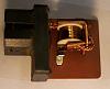
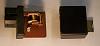
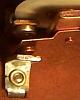
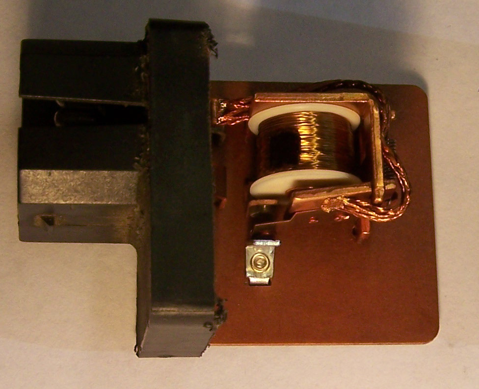
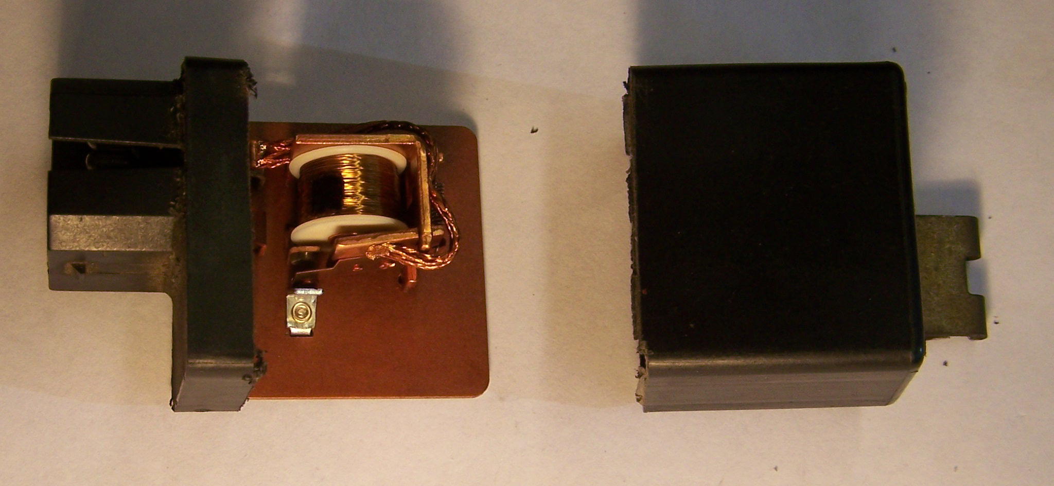
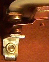
Apparently these fail regularly. Looking at the guts of the thing (see photo) no wonder! This relay, (Volvo 899931 1323592-1, 12V 40A) stuck to the water reservoir bracket on the right front on some 740�s, doesn�t look anything like a 40A relay! The contacts can�t even handle 3A on a regular basis!
The relay powers the + rail of the injector array (green wire on the injectors which are wired in parallel). They get activated by a minus pulse on the grey wire from the ECU. You could bare one of the green injector wires (roll the rubber back a bit) and stick a meter on it when trying to start the car. It should read about 12V.
To check the radio interference suppression relay (geez � I love that description), unplug it and measure the voltage of the yellow wire with green stripe that goes into the plug. It should read +12 V with the ignition on. Then plug the relay back in. If you don�t get 12V on the green injector wire with ignition on check the relay for defects.
It�s possible to fix these by carefully hacksawing the cover off near the base (see photo) and cleaning the point with abrasive paper. Mine read anything from 3 ohms to 50 ohms between the points with the relay on - the perfect intermittent fault. That went down to 0 ohm after cleaning.
OK, the re-location of that relay away from the radio (where they apparently had problems with it) eliminates or minimises radio interference, but the relay itself doesn�t and can�t suppress radio interference, so it�s a total misnomer. Radio interference apparently was caused in the first place (see elsewhere in this thread) by moving all the relays in the 1990�s Volvo 740 directly under the radio behind the ashtray at the back of the fuse box where nobody can get at them. The wires carrying the injector pulse return load radiated interference into the AM. Radio interference suppression is not the relay�s function and does not describe what it does. The relay�s only function is to keep the engine going. It supplies the power to the fuel injectors. Take that away and you�ve got no car!
Apparently these fail regularly. Looking at the guts of the thing (see photo) no wonder! This relay, (Volvo 899931 1323592-1, 12V 40A) stuck to the water reservoir bracket on the right front on some 740�s, doesn�t look anything like a 40A relay! The contacts can�t even handle 3A on a regular basis!
The relay powers the + rail of the injector array (green wire on the injectors which are wired in parallel). They get activated by a minus pulse on the grey wire from the ECU. You could bare one of the green injector wires (roll the rubber back a bit) and stick a meter on it when trying to start the car. It should read about 12V.
To check the radio interference suppression relay (geez � I love that description), unplug it and measure the voltage of the yellow wire with green stripe that goes into the plug. It should read +12 V with the ignition on. Then plug the relay back in. If you don�t get 12V on the green injector wire with ignition on check the relay for defects.
It�s possible to fix these by carefully hacksawing the cover off near the base (see photo) and cleaning the point with abrasive paper. Mine read anything from 3 ohms to 50 ohms between the points with the relay on - the perfect intermittent fault. That went down to 0 ohm after cleaning.
no mo volvo
Joined: Oct 2010
Posts: 11,289
Likes: 109
From: 37 North on the left coast
I wouldn't use abrasives, you don't wnat to remove whats left of the plating on those contacts or they'll corrode real fast. I use DeOxit (a contact cleaner oil) and a bit of cotton cloth to clean contacts, or if they are real bad and I can get to them, a clean soft pink pencil eraser.
its a $50 relay for a /real/ one made by Stribel from davebarton.com A Kaeler (KAE) relay is $30. here's a KAE for $21, Volvo Relay KAE 109318 KAE-1323592
its a $50 relay for a /real/ one made by Stribel from davebarton.com A Kaeler (KAE) relay is $30. here's a KAE for $21, Volvo Relay KAE 109318 KAE-1323592

Senior Member
Joined: Jan 2011
Posts: 1,210
Likes: 14
From: New York
Radio Interference Suppression Relay � that�s got to be one of the most misleading descriptions ever! It�s also perfect for planned obsolescence � the car�s symptoms of intermittent fault, no starting, sudden loss of power and general unreliability are often put down to the car being old and obsolete, so it�s easy to think it�s time for a new car. It should be called the Fuel Injector relay � but you won�t find that description on any circuit diagram.
OK, the re-location of that relay away from the radio (where they apparently had problems with it) eliminates or minimises radio interference, but the relay itself doesn�t and can�t suppress radio interference, so it�s a total misnomer. Radio interference apparently was caused in the first place (see elsewhere in this thread) by moving all the relays in the 1990�s Volvo 740 directly under the radio behind the ashtray at the back of the fuse box where nobody can get at them. The wires carrying the injector pulse return load radiated interference into the AM. Radio interference suppression is not the relay�s function and does not describe what it does. The relay�s only function is to keep the engine going. It supplies the power to the fuel injectors. Take that away and you�ve got no car!
Apparently these fail regularly. Looking at the guts of the thing (see photo) no wonder! This relay, (Volvo 899931 1323592-1, 12V 40A) stuck to the water reservoir bracket on the right front on some 740�s, doesn�t look anything like a 40A relay! The contacts can�t even handle 3A on a regular basis!
The relay powers the + rail of the injector array (green wire on the injectors which are wired in parallel). They get activated by a minus pulse on the grey wire from the ECU. You could bare one of the green injector wires (roll the rubber back a bit) and stick a meter on it when trying to start the car. It should read about 12V.
To check the radio interference suppression relay (geez � I love that description), unplug it and measure the voltage of the yellow wire with green stripe that goes into the plug. It should read +12 V with the ignition on. Then plug the relay back in. If you don�t get 12V on the green injector wire with ignition on check the relay for defects.
It�s possible to fix these by carefully hacksawing the cover off near the base (see photo) and cleaning the point with abrasive paper. Mine read anything from 3 ohms to 50 ohms between the points with the relay on - the perfect intermittent fault. That went down to 0 ohm after cleaning.
Attachment 12881
Attachment 12882
Attachment 12883