
Brake Light Failure


Thread Starter
|
Junior Member
Joined: Oct 2012
Posts: 7
Likes: 0
From: Nashville, TN
Hello Everyone!
I am always thankful for this forum. I can't tell you how many times you've helped me fix my 89, 240 sedan. Unfortunately, I have another problem.
All of my brake lights failed simultaneously. After reading a bunch of threads, I have checked and replaced the fuse, replaced any necessary bulbs, cleaned up the taillight circuit, checked and cleaned all the taillight grounds, and used a volt meter to check the power from the fuse box.
If I understand everything right, the power should run from the fuse box to the brake light switch to the red, round relay under the dash. Is this correct? At first, I thought the brake switch was bad, but then I noticed that I'm not even getting power to the brake switch.
Does that mean there's a problem between the fuse box and the switch? Or is it possible that I've misunderstood the power flow and the relay could be malfunctioning somehow?
Thanks for all your help! I look forward to hearing from you.
Jamie

no mo volvo
Joined: Oct 2010
Posts: 11,289
Likes: 109
From: 37 North on the left coast
per the 1989 240 greenbook...
battery - red wire - positive terminal (on left fender well under hood)
positive terminal - red wire to input side of fuse 6 (which is connected to fuses 7-8-9-10 in the fuse panel)
fuse 7 - green-red wire to brake switch pin 1
brake switch pin 2 - blue-red wire to lamp failure sensor pin 9
lamp failure sensor pin 5 - blue-black wire to upper brake light.
lamp sensor pin 11 - yellow wire to right brake light
lamp sensor pin 10 - yellow-green wire to left brake light.
and thats all she wrote...
so... fuse 7, both sides, should be +volts at all times, and that green-red wire at the brake switch should be always-hot too. there is no relay in the circuit.
a note on the 240 fuse panel, each fuse has 3 spade lugs immediately to the right of it (behind the plastic kick panel). the RIGHT/REAR most spade lug is connected to the LEFT side of the fuse and is the input. the middle and left/frontmost spade lugs are both connected to the RIGHT side of the fuse and are the outputs. some fuses, ,like 6-10, have their inputs wired together inside the fuse panel.
Thread Starter
|
Junior Member
Joined: Oct 2012
Posts: 7
Likes: 0
From: Nashville, TN
Pierce!
Thanks so much for the details! This is really helpful.
I started doing some digging around under the dash. I wanted to follow all the wires and make sure I checked everything for power again.
I'm a little confused by what I found. I'm hoping you guys can help me. I did my best to take pictures, though they didn't turn out great.
Alright, so if I followed everything correctly. The green/red wire leaves the fuse box and connects to a huge bundle that runs under the dash. As it nears the under part of the center console (close to the drivers feet) the green/red and the blue/red leave the bundle and run to this thing above the brake pedal. I couldn't get a great view of it, but as far as I can tell it doesn't seem to have a switch at the end of it that touches the brake pedal. Here's a picture of the top side (side closest to the driver):
https://drive.google.com/file/d/0Bxz...ew?usp=sharing
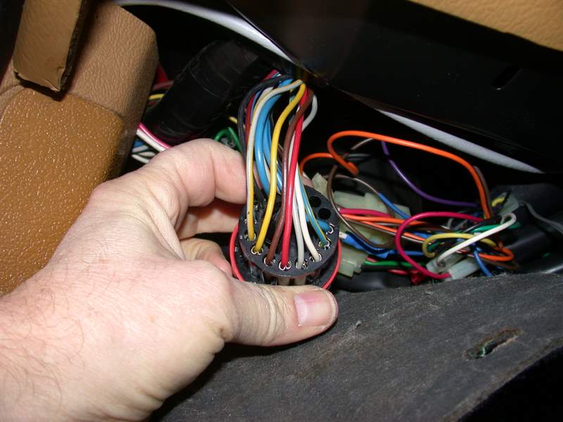
From there, a green/white wire runs to what I think is the brake switch. It sits just above the brake pedal, has a switch at the end that is compressed when the brakes are not in use, and there is a vacuum line attached to the top.
I tried to get some images of the wires and the switch:
https://drive.google.com/file/d/0Bxz...ew?usp=sharing
https://drive.google.com/open?id=0Bx...lJV&authuser=0
From that switch the blue/red goes to another switch above the clutch and from there goes to a bundle of wires that connect to the cruise control module with a harness.
It was tough to access but I checked the power from the fuse box to the first connection I pictured. The green/red has power, but the green/white doesn't. I couldn't get the volt meter to touch the blue/red without some help. So, I'm not sure if it is hot or not.
Can anyone help me understand what I'm dealing with here?
Thanks
Jamie
Thanks so much for the details! This is really helpful.
I started doing some digging around under the dash. I wanted to follow all the wires and make sure I checked everything for power again.
I'm a little confused by what I found. I'm hoping you guys can help me. I did my best to take pictures, though they didn't turn out great.
Alright, so if I followed everything correctly. The green/red wire leaves the fuse box and connects to a huge bundle that runs under the dash. As it nears the under part of the center console (close to the drivers feet) the green/red and the blue/red leave the bundle and run to this thing above the brake pedal. I couldn't get a great view of it, but as far as I can tell it doesn't seem to have a switch at the end of it that touches the brake pedal. Here's a picture of the top side (side closest to the driver):
https://drive.google.com/file/d/0Bxz...ew?usp=sharing
From there, a green/white wire runs to what I think is the brake switch. It sits just above the brake pedal, has a switch at the end that is compressed when the brakes are not in use, and there is a vacuum line attached to the top.
I tried to get some images of the wires and the switch:
https://drive.google.com/file/d/0Bxz...ew?usp=sharing
https://drive.google.com/open?id=0Bx...lJV&authuser=0
From that switch the blue/red goes to another switch above the clutch and from there goes to a bundle of wires that connect to the cruise control module with a harness.
It was tough to access but I checked the power from the fuse box to the first connection I pictured. The green/red has power, but the green/white doesn't. I couldn't get the volt meter to touch the blue/red without some help. So, I'm not sure if it is hot or not.
Can anyone help me understand what I'm dealing with here?
Thanks
Jamie
Last edited by j.cunningham; Apr 15, 2015 at 10:29 PM.
no mo volvo
Joined: Oct 2010
Posts: 11,289
Likes: 109
From: 37 North on the left coast
my 1989 wiring diagrams don't include the cruise control, but that vacuum switch thing sounds like its part of it. IIRC< the cruise on our 87 240 had a vacuum actuator near the pedals that actually pulled the gas pedal lever, rather than a cable to the throttle spool under the hood.
Thread Starter
|
Junior Member
Joined: Oct 2012
Posts: 7
Likes: 0
From: Nashville, TN
So, I still haven't figured this out yet.
Is it possible for by brake lights, and reverse lights to completely fail due to a faulty ground somewhere?
The tail lights work fine.
Thanks in advance for the help!
Is it possible for by brake lights, and reverse lights to completely fail due to a faulty ground somewhere?
The tail lights work fine.
Thanks in advance for the help!

Junior Member
Joined: Sep 2016
Posts: 18
Likes: 1
From: near Baltimore
If you're sure the fuse is passing current, the most likely fault in your brake lights causing all of them to quit is not in the switch, but in the bulb failure warning sensor. You can reach that a lot easier than reaching the brake lamp switch, and get your meter or test light probe on the wire ends going into its big socket.
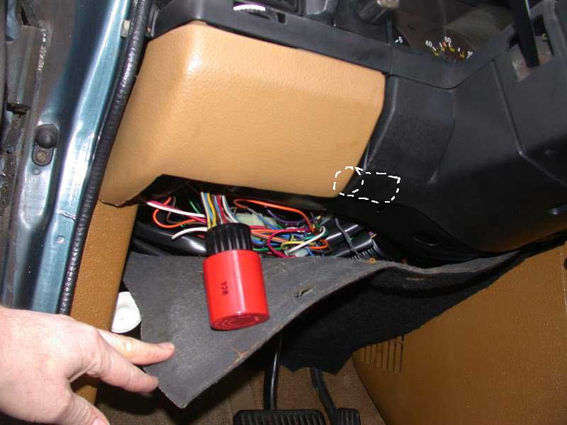
I'm not sure what year/model, but if 89 as referred to in pierce's response, the above is what yours will look like. Let us know for sure what model/year and we can tell you what to read where, as the wire colors had some changes year/year.
Edit: I see you clearly stated year and model, I just forgot it by the time I read on. The colors of the wires you need to measure:
Blue/red - 12V from brake light switch to BFWS.
Yel/gray - to Left Brake Lamp.
Yellow - to Right Brake Lamp.
Blue/black - to 3rd (high mounted) Brake Lamp.
With your foot on the brake pedal, check for voltage on these four points on the BFWS relay. That should tell you more about where the trouble is.
If you still think it might be the pedal switch, here are some tips getting to that thing:
240 Volvo: Replacing the Brake Light Switch
Last edited by cleanflametrap; Oct 28, 2016 at 10:58 AM.

Thread
Thread Starter
Forum
Replies
Last Post
cheebster
Volvo XC90
2
May 8, 2014 04:31 PM
rburner
Volvo S80
2
Apr 19, 2011 09:14 AM
kosmoscanyon
Volvo V70
5
Dec 16, 2008 12:39 PM
soulfulimpressions
Volvo V70
15
Jul 31, 2008 07:07 PM