
Replaced Fuel Sending Unit, Gauge reads full all the time?


Thread Starter
|
Junior Member
Joined: Aug 2012
Posts: 26
Likes: 0
Chaps...
When I purchased my vehicle, the fuel gauge wasn't working... this was diagnosed as being a faulty sending unit. I ordered a new one, and installed it, and now my fuel gauge is functioning... but it's only reading full? When the key is out, it sinks back to empty.
Thoughts... I'm sure I have a wire reversed somewhere, though I tried to read the cleanflametrap site carefully.

Senior Member
Joined: Jan 2006
Posts: 1,797
Likes: 52
Did you purchase an aftermarket sending unit or the original equipment ones? The aftermarket ones are notorious for having all of the wiring backwards. I replaced the unit in my '90 240 with an aftermarket unit and I found that the black connector had the two wires in it switched. Prior to installation, I compared the new unit against my old one just to check out the wiring. The black keyed connector had the fuel pump wire connected to the sending unit & vice versa. It may also have had the two wires that run to the fuel pump switched which would make the fuel pump run backwards.
I'd pull the unit out and verify all of the wiring by comparing it to the old unit.
I'd pull the unit out and verify all of the wiring by comparing it to the old unit.
Thread Starter
|
Junior Member
Joined: Aug 2012
Posts: 26
Likes: 0
I did check the wiring, but now that you mention it... I don't recall if the fuel sender and pump wires were switched. I did switch the connections around for the pump though to make it run correctly... or so I hope...
Regardless, the car runs just fine, so if the pump is bad or not isn't my main concern (that sounds snarky... I don't mean it to sound snarky )... I just want the gauge to work.
I'm wondering if I've got a bad ground... I'm no good with electrics though.
Regardless, the car runs just fine, so if the pump is bad or not isn't my main concern (that sounds snarky... I don't mean it to sound snarky
)... I just want the gauge to work.I'm wondering if I've got a bad ground... I'm no good with electrics though.
Senior Member
Joined: Jan 2006
Posts: 1,797
Likes: 52
Have you double-checked that the in-tank pump is running? If not, go back and check it. Pull fuse #4 and jumper the right side of fuse #4 holder with fuse #6. This should run the in-tank pump (check here for instructions In the Tank - 240 Volvo Tank Pump and Sender). If the in-tank pump is running fine, then certainly it is not the black keyed connector. If the pump does not run, it could be that the two wires are switched in the black keyed connector.
To check the wires in the connector, the yellow/red wire from the wiring harness should be connected to the black wire running to the fuel pump.
Good luck
To check the wires in the connector, the yellow/red wire from the wiring harness should be connected to the black wire running to the fuel pump.
Good luck
Thread Starter
|
Junior Member
Joined: Aug 2012
Posts: 26
Likes: 0
Thanks Act... question though... if the wires were backwards, wouldn't the pump simply run backwards?
I'm going to double check it Monday... I'm going to Black River Stage Rally this weekend, so I won't have time... I don't think...
I'm going to double check it Monday... I'm going to Black River Stage Rally this weekend, so I won't have time... I don't think...
Senior Member
Joined: Jan 2006
Posts: 1,797
Likes: 52
If the two wires inside the tank that attached directly to the fuel pump were switched, yes, the pump would run backwards.
However, what I am referring to is the black keyed connector outside the tank. There are three wires that go into the tank - ground (brown), fuel pump (black) and fuel sending unit (gray). The brown wire gets bolted to a grounding post outside the tank while the black and brown wire go to a keyed connector that connects into the wiring harness. I have found those two wires switched on the aftermarket unit. When this is the case, the +12v that is supposed to go to the fuel pump will be applied to the fuel sending unit and vice versa.
Good luck
Thread Starter
|
Junior Member
Joined: Aug 2012
Posts: 26
Likes: 0
Ahhh yes... I know what you mean now.
I'll double check them. When I pulled the previous unit out of the vehicle, I matched all the wiring, as well as compared it to what was on CFT's website. So I thought at least... but TBPH, I wouldn't be surprised if I missed something.
Obviously something isn't right, because the damn thing isn't working right. lol...

Junior Member
Joined: Apr 2013
Posts: 3
Likes: 0
My new IDP sender seemed to be wired up fine, but what I didn't check was whether or not the wires in the connector were oriented correctly. Sure enough my fuel gauge pegged out and pump wouldn't run. I checked and the plastic part holding the two connectors had them switched. I just popped them out and reinserted into the holder and everything works fine now.

Senior Member
Joined: Mar 2010
Posts: 218
Likes: 0
One thing to check:
I've had fuel gauges fail, and an easy test I've found to determine if the sending unit is bad, or if the gauge is bad is disconnect the sending unit harness where it is taped down to some black gunky stuff and jump a wire from the terminal to the ground wire, and if the gauge is good, it will go to full, if the gauge is bad, nothing will happen.
Do you happen to have the ground wire touching the positive anywhere?

no mo volvo
Joined: Oct 2010
Posts: 11,289
Likes: 109
From: 37 North on the left coast
yall realize, this is a year old thread?
re: that jumpering fuse 4 to 6 stuff, thats 240 specific, I don't see up there where the OP says what model car they are working with.
re: that jumpering fuse 4 to 6 stuff, thats 240 specific, I don't see up there where the OP says what model car they are working with.
Senior Member
Joined: Jan 2006
Posts: 1,797
Likes: 52
Having the two wires switched in the black connector will not make the pump run backwards. The black connector has two wires: Yellow/Red wire provide 12v to pump. Gray wire is signal to fuel guage. This is on the wiring harness side of the black connector. Ground for the pump and fuel guage does not go through the connector but is instead a ground lug near the black connector.
In the aftermarket sending units, the gray wire ends up connected to the pump giving it a a low resistance to ground. This results in a full reading the fuel guage. The 12v intended for the pump ends up going to the fuel guage sending unit (like the center tap on a potentiometer). If you had a full tank, this would mean nearly a short on the pump 12v and most likely blow the fuse.
To answer your question Pierce, yes it is an old thread. It is nice to see some of the users here search the archives for their answers rather than post a new thread each time.
Junior Member
Joined: Apr 2013
Posts: 3
Likes: 0
I know this is an old thread but I figure until all these are scrapped people who own them may be still having similar problems. I am talking about the sender on a 1986 240 btw. I did make an assumption that the OP was referring to a 240 as well.
From my measurements the pump resistance was less than 3Ω while the sender was over 30Ω full and around 300Ω empty. I'm surprised the cross wiring didn't toast the sensing circuit or fry the top end of the sending unit. In either case the current should have been less than 2A but still about 10x what the entire fuel gauge sending circuit would see under normal operations.
From my measurements the pump resistance was less than 3Ω while the sender was over 30Ω full and around 300Ω empty. I'm surprised the cross wiring didn't toast the sensing circuit or fry the top end of the sending unit. In either case the current should have been less than 2A but still about 10x what the entire fuel gauge sending circuit would see under normal operations.

Junior Member
Joined: Mar 2011
Posts: 4
Likes: 0
Hi,
Yes, this is an old thread, but these are old cars. I am about to install an aftermarket fuel sending unit in my 1993 Volvo 240 wagon. I want to correct (or confirm) the wiring on the aftermarket unit before I remove the old unit. Above, someone describes the wiring to the black keyed connector as follows:
Black: Pump
Grey: Sender
Brown: Ground
It's been said that the following two wiring errors are common with aftermarket fuel sending units:
1. The black and grey wires going into the black keyed connector are reversed.
2. The black and yellow wires going into the pump are reversed and cause the pump to run backwards.
My questions are:
1. With the beveled side facing up and the end of the black keyed connector facing me, on which side (left or right) should the black and grey wires be?
2. With the soldered pump terminal connectors facing out toward me, on which side (left or right) should the black and yellow wires be?
I've checked here, Brickboard, and other forums. The issue is commonly discussed, but nobody's written down what the correct wiring actually looks like. Could anyone help? Thank you!
Junior Member
Joined: Mar 2011
Posts: 4
Likes: 0
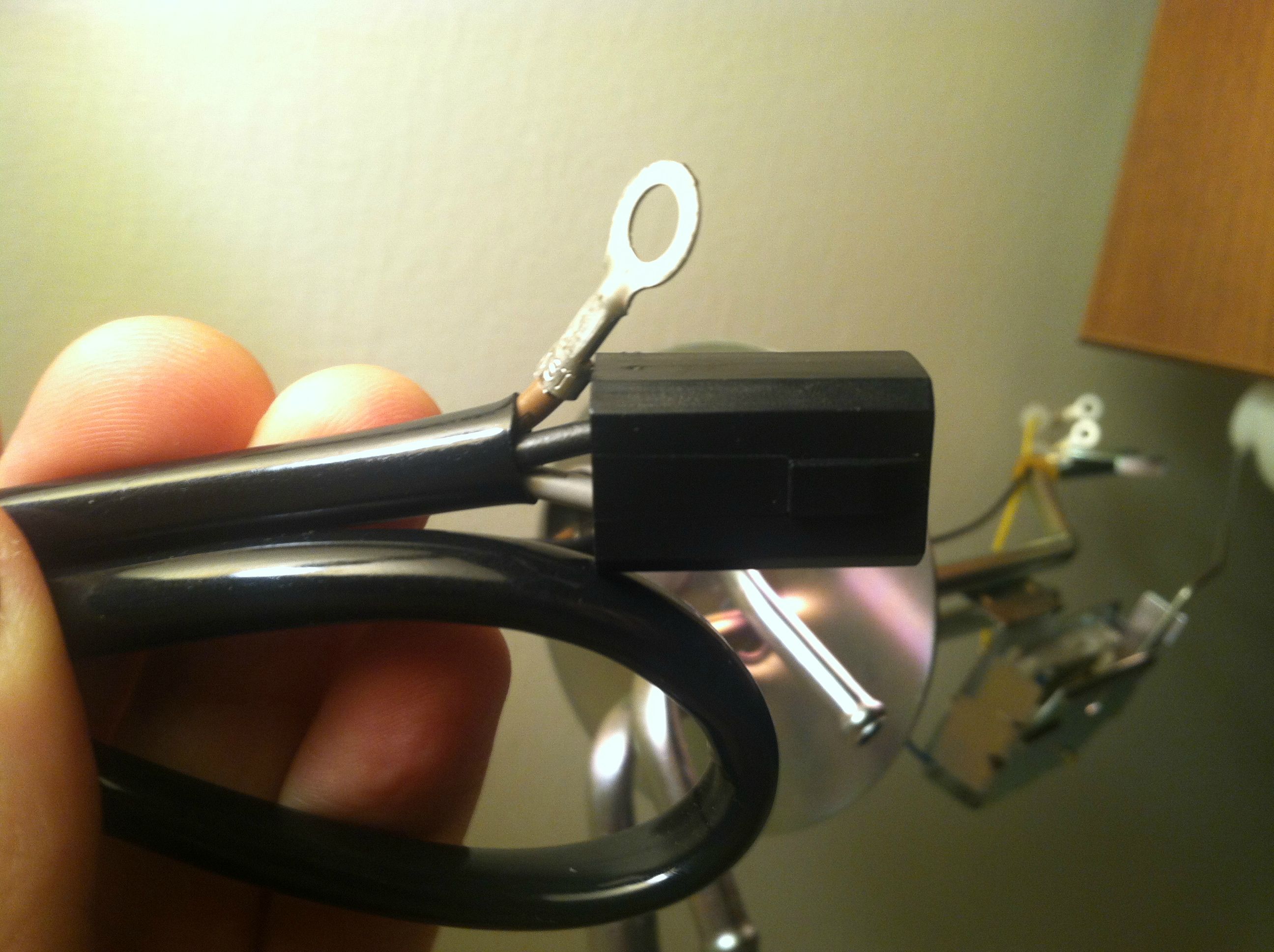
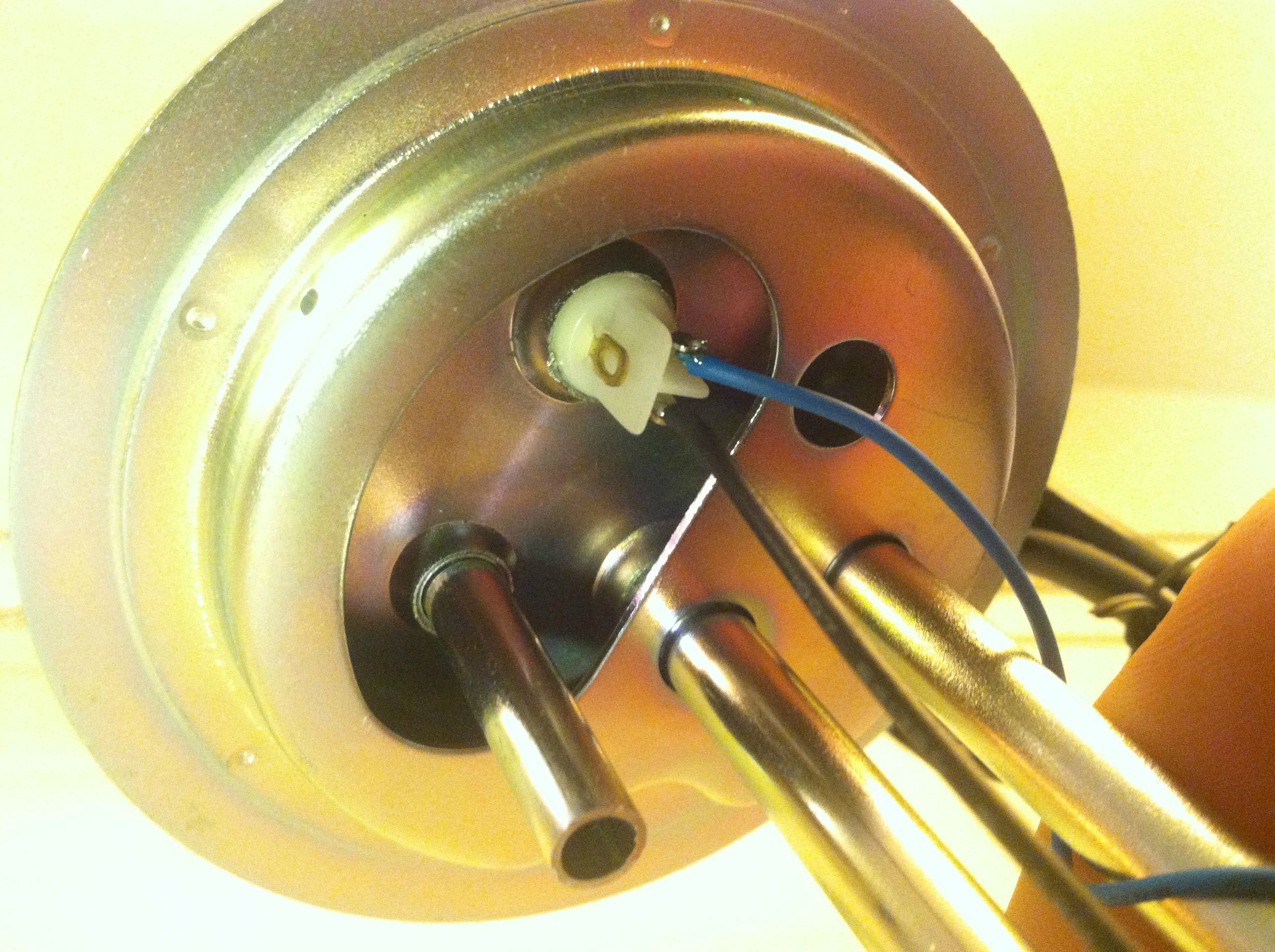
Better yet, here are pictures of the aftermarket fuel sending wiring as it came out of the box. Is this correct?
In-tank pump wiring (yellow and black):
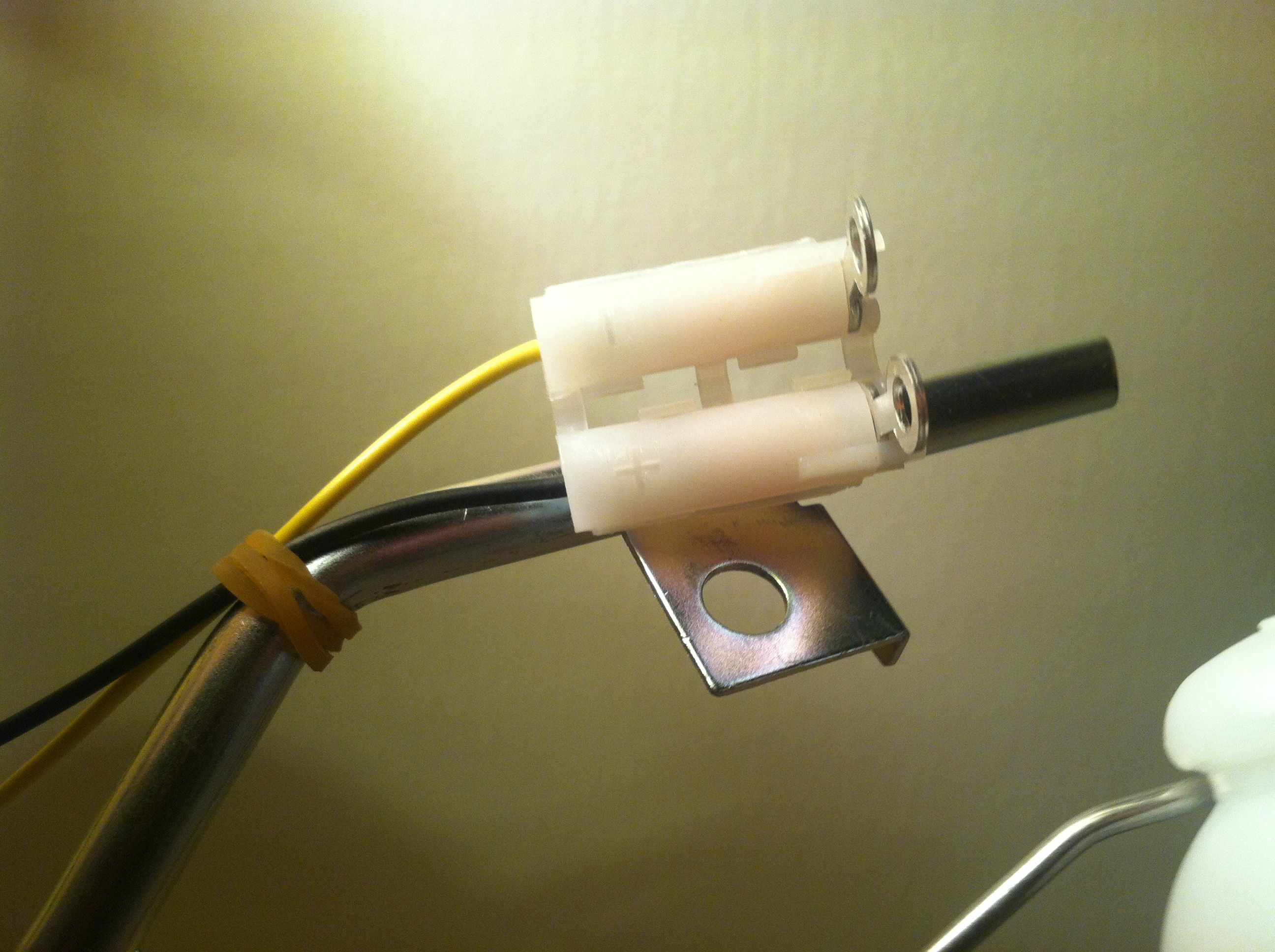
Outside tank wiring: sending unit, pump, and ground (grey/black/brown)
In-tank wiring, underside of cap:
In-tank pump wiring (yellow and black):
Outside tank wiring: sending unit, pump, and ground (grey/black/brown)
In-tank wiring, underside of cap:
Senior Member
Joined: Jan 2006
Posts: 1,797
Likes: 52
To verify the proper wiring, remove the old unit and place them on the bench side-to-side and compare the wire routing. Also compare the location of the gray and black wire in the keyed connector. This is the best way to verify the wiring.
Since my earlier posts on this thread, I ran into a third problem with the aftermarket unit. Mine stopped working last winter and when I pulled it found the float filled with gasoline. There was a tiny pinhole in the float that was there from when it was injection molded. It was very thin in one place. Take the float and submerse it in a bowl of water and squeeze. Make sure no bubbles come out. If it were me, I'd save the float from the old unit just in case (wish I had).
Since my earlier posts on this thread, I ran into a third problem with the aftermarket unit. Mine stopped working last winter and when I pulled it found the float filled with gasoline. There was a tiny pinhole in the float that was there from when it was injection molded. It was very thin in one place. Take the float and submerse it in a bowl of water and squeeze. Make sure no bubbles come out. If it were me, I'd save the float from the old unit just in case (wish I had).
Last edited by act1292; Dec 1, 2015 at 06:13 AM.
Junior Member
Joined: Mar 2011
Posts: 4
Likes: 0
Thank you. I read about that problem on the cleanflametrap article, so I was planning on just using the floater ball off the original to prevent this.
I was hoping to determine this before removing the old unit to prevent bringing out the soldering iron after getting exposed to gas fumes. Any additional info would be much appreciated!
I was hoping to determine this before removing the old unit to prevent bringing out the soldering iron after getting exposed to gas fumes. Any additional info would be much appreciated!
Junior Member
Joined: Mar 2011
Posts: 4
Likes: 0
Based on the photos in this volvoforums.org.uk thread, the aftermarket fuel sending unit I received was wired correctly out of the box:
240 General: - Replacement of Intank Fuel Pump on Volvo 240. - Volvo Owners Club Forum
240 General: - Replacement of Intank Fuel Pump on Volvo 240. - Volvo Owners Club Forum

Thread
Thread Starter
Forum
Replies
Last Post
vwzoo
Volvo 240, 740 & 940
3
May 21, 2013 12:26 PM
jold
Volvo 240, 740 & 940
1
Nov 5, 2010 08:23 PM