
PCV system service troubles 94 850 n/a - help please!


Thread Starter
|
Member
Joined: Sep 2013
Posts: 62
Likes: 0
From: Glendale, WI
Hello again good people of volvoforums, I come to you seeking help and advice. I started the PCV system on my 94 850 N/A today, and it was BAD:
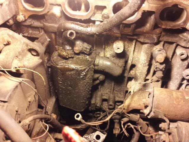
In the process, I discovered a few discrepancies that didn't seem to match up with the videos/instruction threads I'd seen for this service. In that regard, I've got a few questions/requests:
1. First on the list is the vacuum tree:
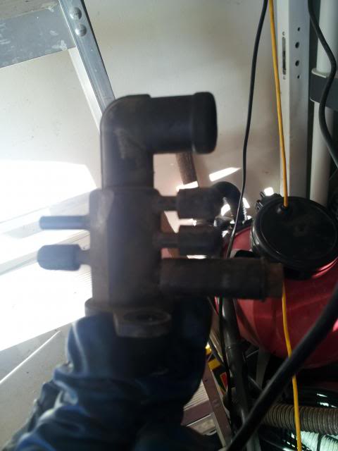
I'm no expert, but that piece of hose with a bolt jammed into it does not appear factory. Was this just a makeshift replacement for a cracked cap, or is there supposed to be a vacuum line running to that spot. For that matter, are all the capped lines supposed to be that way? I was under the impression that there should be at least 2 vacuum lines running to the tree.
2. Is there supposed to be a hose connected to the little component on the underside of the intake manifold seen here?:
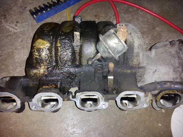
There was definitely nothing connected to it, which seems iffy. Additionally, could someone clue me in to what exactly this component is? I believe it is the choke control, but am not sure. If it is, where in the world is the vacuum line going to it supposed to be coming from?
3. How critical is the intake manifold support bracket? I ask because whoever worked on this car last decided that it was a good idea to leave it out and as such, I do not have one.
4. Just to be on the safe side, would someone be kind enough to provide me with a list of hoses in the PCV system and where they're supposed to go to and from? I would usually just go by the replace what's there method, but judging by the way everything looks I fear the previous owner may have botched an attempted PCV replacement and as such I can't just rely on putting hoses back into the same spots that I found them.
This car is meant as a replacement for my condemned daily driver, and I need it to be up and running relatively soon. The PCV kit was the last service on my list, and I am afraid that if I proceed on my own I may end up with a non-drivable car. Thank you for any assistance you can lend!
Last edited by awfulwaffle; Sep 23, 2013 at 11:46 PM.

Administrator
Joined: Mar 2009
Posts: 15,736
Likes: 36
From: Albuquerque, NM
Was the car running before you started? As for the tree, people do plug vacuum holes/leaks with anything they can find. It's possible that only 1 thing needs to be connected to it but I'm not sure.
Not sure what is bolted to the bottom of the intake, Volvo had a habit of trying things when it came to the pre '95 cars.
On the NA cars, there is the tube that goes to the top of the motor, and the tube that goes to the flame trap & side of the manifold, not much other than that.
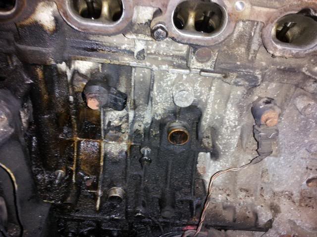
In the photo, it appears that one of the knock sensors have the connection missing?
Wouldn't worry to much about the manifold support bracket, my guess is it was removed because someone had it off to replace a starter or alternator. Doesn't look like anyone has ever tried to replace the PCV system.
Not sure what is bolted to the bottom of the intake, Volvo had a habit of trying things when it came to the pre '95 cars.
On the NA cars, there is the tube that goes to the top of the motor, and the tube that goes to the flame trap & side of the manifold, not much other than that.
In the photo, it appears that one of the knock sensors have the connection missing?
Wouldn't worry to much about the manifold support bracket, my guess is it was removed because someone had it off to replace a starter or alternator. Doesn't look like anyone has ever tried to replace the PCV system.

You have the 20V engine with the variable intake manifold, the so called V-VIS. The engine ECU (you have 2 btw 1 for the injection, a second for ignition) can asses when the engine needs full power and activates this valve which trigers some flaps inside the manifold. I have the same engine in my car 
This cars were build from 92 up to 96, in 96 Volvo switched to the Motronic 4.4 (you have the LH 3.2), 96 models can have either systems, from 97 only Motronic.
The valve in your pic is triggered by an electric valve which is attached to your air filter box. Nr 17 in the first pic, the Valve should be located between the air filter box and distributer cap bolted with 2 Torx 25 screws onto the air box.
Don't bother with the vacuum tree the owner just sealed it off, otherwise you would have an air leakeage which is bad for the 20V engine as it has an MAF which reacts very allergic to air leaks.
From the PCV box one hose goes up to the cylinder head and the second to the right along the intake manifold and ends right before the throttle body. There it has the flame trap which you can ditch.
From the pics I also see that you have some ground wires which are not conected this is also bad.
Cristian
Last edited by scutyde; Sep 24, 2013 at 07:38 AM.
Thread Starter
|
Member
Joined: Sep 2013
Posts: 62
Likes: 0
From: Glendale, WI
Thank you for the replies, guys!
RSPI:
The car was running when I got it, though it did have an intermittent misfire, started a little hard in the morning and was blowing smoke/oil out of the valve cover as well as from underneath the intake manifold (I can now see exactly where the leak underneath was coming from lol). I figured that the previous owner had attempted the PCV system judging by the fact that some of the hoses had screw type hose clamps, and some had no clamps at all. The knock sensor I disconnected to give myself a little more room, the plug is still there and hanging out of the way. Good to know that I don't absolutely need the support bracket though.
Scutyde:
Those diagrams are very helpful, thank you. Would it be alright for me to PM you if I have any more specific questions, given that you have the same engine in your car? Hopefully I won't need to, but it would be nice to have the option.
On the note of the grounds, those were actually attached to the oil dipstick tube support bolt, which is why they are hanging down and unoccupied at the moment. I take it that this isn't supposed to be the way they're attached?
Last edited by awfulwaffle; Sep 24, 2013 at 12:45 PM.
Shoot anytime Just mind the time zone differences 
Actually I would suspect that the cables belong more to the right near the starter motor. Clean a little bit the "mess" there with brake cleaner or so because it's really hard to tell where they belong...Which color do the cables have? If they are brown then I suspect they are the 31/33, black 31/32... Personally I would get a support bracket from the junkyard, any 850 & V70 up to 99 should fit. You are stressing the cylinder head which I don't think is such a good thing.
Cristian
Just mind the time zone differences Actually I would suspect that the cables belong more to the right near the starter motor. Clean a little bit the "mess" there with brake cleaner or so because it's really hard to tell where they belong...Which color do the cables have? If they are brown then I suspect they are the 31/33, black 31/32... Personally I would get a support bracket from the junkyard, any 850 & V70 up to 99 should fit. You are stressing the cylinder head which I don't think is such a good thing.
Cristian
Last edited by scutyde; Sep 24, 2013 at 01:18 PM.

Administrator
Joined: Mar 2010
Posts: 4,517
Likes: 12
From: Cape Coral, FL
+1 on replacing that support. When you hold that manifold and consider all that is hanging off those intake bolts into the head that's a lot of weight when you hit a bump. Over time it could compress the intake gasket on the lower edge and open up a vacuum leak at the top.
Administrator
Joined: Mar 2009
Posts: 15,736
Likes: 36
From: Albuquerque, NM
I also agree on the bracket, I just wouldn't park the car waiting on it. Hope I didn't give the impression that it wasn't necessary. Just install it when you can. No hurry to me. I would get it done within a few weeks.
Thread Starter
|
Member
Joined: Sep 2013
Posts: 62
Likes: 0
From: Glendale, WI
Understood, I'll be heading back to the scrapyard tomorrow because the terminal snapped off of the starter I snagged from them >.< , so I can get my hands on the bracket then.
Managed to work on the car for another hour or so after class and before work today, and made a few more discoveries. SCUTYDE, you were spot on with your advice; both 31/32 and 31/33 were inexplicably bolted to the dipstick support bracket instead of the positions shown in the diagram you provided. Of course, there were no bolts in those holes, so I'll have to get my hands on some tomorrow as well.
Got a hold of a vacuum diagram for the n/a 850, and made a discovery concerning what I now know is the V-VIS system: The bolt/hose plugged position on the vacuum tree is the one for the hose that is supposed to run to the V-VIS solenoid valve, and the line that was supposed to run to the vacuum actuator was plugged with a nail.
This leads me to the following questions:
1. Can anyone think of any reason one would want to disconnect the V-VIS system? From what I understand, it's supposed to default to the open position, so even if there was a fault somewhere in the solenoid or vacuum actuator nothing would be any different.
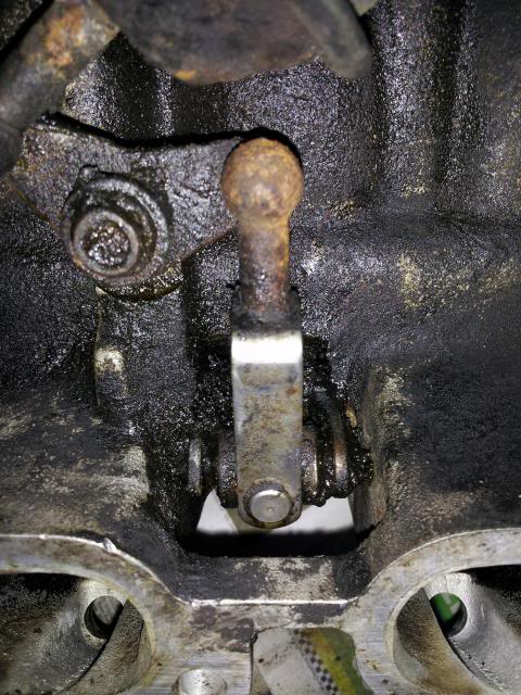
2. Is there perhaps a way to make sure the VVIS assembly is functioning properly? I do not have a vacuum source I can use to operate the actuator that way. I did, however, check if the actuator seen below actually moves, and it does to a point. Namely, it will move the flaps in the intake manifold (not all the way), but takes a bit of force. There also does not seem to be any kind of return spring feel to the flaps/actuator, I had to pull it back open by hand. If this is indeed a problem, is my only option to try and get a manifold with a working V-VIS system? (I feel like this last question may deserve its own thread.)
Again, many thanks to everyone who is willing to take the time out of their day to help this Volvo noob out.
Managed to work on the car for another hour or so after class and before work today, and made a few more discoveries. SCUTYDE, you were spot on with your advice; both 31/32 and 31/33 were inexplicably bolted to the dipstick support bracket instead of the positions shown in the diagram you provided. Of course, there were no bolts in those holes, so I'll have to get my hands on some tomorrow as well.
Got a hold of a vacuum diagram for the n/a 850, and made a discovery concerning what I now know is the V-VIS system: The bolt/hose plugged position on the vacuum tree is the one for the hose that is supposed to run to the V-VIS solenoid valve, and the line that was supposed to run to the vacuum actuator was plugged with a nail.
This leads me to the following questions:
1. Can anyone think of any reason one would want to disconnect the V-VIS system? From what I understand, it's supposed to default to the open position, so even if there was a fault somewhere in the solenoid or vacuum actuator nothing would be any different.
2. Is there perhaps a way to make sure the VVIS assembly is functioning properly? I do not have a vacuum source I can use to operate the actuator that way. I did, however, check if the actuator seen below actually moves, and it does to a point. Namely, it will move the flaps in the intake manifold (not all the way), but takes a bit of force. There also does not seem to be any kind of return spring feel to the flaps/actuator, I had to pull it back open by hand. If this is indeed a problem, is my only option to try and get a manifold with a working V-VIS system? (I feel like this last question may deserve its own thread.)

Again, many thanks to everyone who is willing to take the time out of their day to help this Volvo noob out.
Last edited by awfulwaffle; Sep 24, 2013 at 10:15 PM.
Administrator
Joined: Mar 2010
Posts: 4,517
Likes: 12
From: Cape Coral, FL
As for why , , , some people just don't have a clue and remove stuff, some think they know what they're doing and try to "improve" by modification and others just see a vacuum leak and plug it because they can't figure out where it's supposed to go.
Kind of depends on who the previous owner was. From the looks of the engine maintenance and repair wasn't high on the list. IMHO, More just get me A to B.
That vacuum motor you could test with a hand held vacuum pump (loaner tool) and the solenoid you'd need to find out if it's 12 volt. If so you could run a FUSED jumper to the battery and test it that way. You might have to clean and lube some of the components if they are that difficult to move but hopefully someone with some experience on that system can give you some pointers.
Last edited by Kiss4aFrog; Sep 24, 2013 at 10:13 PM.
Be a men and try sucking  No really this is how I tested if it works. Put a hose in it and try it by mouth...It should move.
From the V-VIS assembly the vacuum goes to the solenoid valve . From the solenoid valve the hose goes alongside the motor towards the front and then splits into a non-return valve (22). The non return valve is connected to the vacuum tree and with the vacuum container (27) which is located under the battery bolted to the carbon filter for the fuel tank venitilation.
While you're at it replace all rubber hoses (the vacuum ones) they outlived their live You can use fuel hoses they are cheap and very durable.
Happy crafting
Cristian
No really this is how I tested if it works. Put a hose in it and try it by mouth...It should move.From the V-VIS assembly the vacuum goes to the solenoid valve . From the solenoid valve the hose goes alongside the motor towards the front and then splits into a non-return valve (22). The non return valve is connected to the vacuum tree and with the vacuum container (27) which is located under the battery bolted to the carbon filter for the fuel tank venitilation.
While you're at it replace all rubber hoses (the vacuum ones) they outlived their live
You can use fuel hoses they are cheap and very durable. Happy crafting
Cristian

Senior Member
Joined: May 2012
Posts: 1,988
Likes: 52
From: Kingsport, TN
Boy, that is interesting. I have a 85 NA and I did not realize it has that variable intake manifold. I will have to figure out if I can tell it's working. I'll also be willing to trace stuff on mine if I can help that way.
I guess one way would be to unhook it and see if it's just as fast, hmmm.
I guess one way would be to unhook it and see if it's just as fast, hmmm.
Thread Starter
|
Member
Joined: Sep 2013
Posts: 62
Likes: 0
From: Glendale, WI
Scutyde:
If that's the way to check, then there is absolutely something wrong with the system. However, I don't think it's necessarily the vacuum actuator, which I'll have to remove the linkage from and try sucking on it while its detached from the flaps.
The issue seems to be that the inside of the intake manifold is horribly gunked up, but only under the flaps (the section of the manifold that is closed off when there is no vacuum running to the actuator, if that makes any sense). It's completely clean above the flaps. I'll take some pictures when I have some time. If I manage to make it to the junk yard between classes today, I'll see if a replacement manifold can be had for cheap.
Firebird:
If you have someone to rev the throttle for you, you should be able to see the little armature between the 3rd and 4th intake manifold runners move as they rev the engine at over 80% throttle. At least that's what I came to understand, given the slew of reading I did last night.
I really appreciate your offer of helping me compare line routing, I'll definitely be in touch if I get lost.
Now, the question is how in the world the manifold got so gunked up in the first place, and whether it's a sign of a larger problem....
Last edited by awfulwaffle; Sep 25, 2013 at 11:48 AM.
Boy, that is interesting. I have a 85 NA and I did not realize it has that variable intake manifold. I will have to figure out if I can tell it's working. I'll also be willing to trace stuff on mine if I can help that way.
I guess one way would be to unhook it and see if it's just as fast, hmmm.
I guess one way would be to unhook it and see if it's just as fast, hmmm.
Thread Starter
|
Member
Joined: Sep 2013
Posts: 62
Likes: 0
From: Glendale, WI
Well, it's settled. Local used Volvo parts dealer is pulling a manifold with a properly working VVIS system and mounting bracket for me tomorrow at a very good price. I did notice when I last drove it that the car didn't have any oomph to it when going from a stop, curious to see how much of a difference a working VVIS system will make.
Still a little concerned, though, as the only place I could think of the goop in the intake manifold coming from is out of the cylinders.
Still a little concerned, though, as the only place I could think of the goop in the intake manifold coming from is out of the cylinders.
Last edited by awfulwaffle; Sep 25, 2013 at 08:53 PM.

Junior Member
Joined: Aug 2013
Posts: 9
Likes: 0
From: Grand Rapids Mi
I am about to tackle this same job so am just starting to research it. I am wondering if this was only used on '92 to some '96 models, what system is used on the later models and can it be retro-fitted to fit? There are some very clean salvage yard v70's nearby and I was just assuming they were interchangeable
Thread Starter
|
Member
Joined: Sep 2013
Posts: 62
Likes: 0
From: Glendale, WI
I don't think any such system was used on later models, just a regular ole intake manifold. Also, from what I understand, the VVIS and non-VVIS motors have slightly different intake port configurations, so the manifold you use must match the head on your motor.
Junior Member
Joined: Aug 2013
Posts: 9
Likes: 0
From: Grand Rapids Mi
Is it necessary to remove the intake and injectors? Would it be possible to service these items by moving or removing a few things in front and accessing it from underneath?
Hope I'm not misusing this thread!
Hope I'm not misusing this thread!
Thread Starter
|
Member
Joined: Sep 2013
Posts: 62
Likes: 0
From: Glendale, WI
I don't see how you could, the manifold hangs down very close to the oil trap so it would be nearly impossible to get at hose clamps and fasteners. That, and I think you'd be hard pressed to install the new oil trap tube without breaking it.
Oh, and the difference in the car is like night and day now that the crankcase pressure is properly relieved. All the smoke and intermittent misfires vanished, no oil smell at all!
Oh, and the difference in the car is like night and day now that the crankcase pressure is properly relieved. All the smoke and intermittent misfires vanished, no oil smell at all!
Last edited by awfulwaffle; Oct 2, 2013 at 11:57 PM.

Thread
Thread Starter
Forum
Replies
Last Post
robingichuhi
Volvo S80
3
Feb 22, 2017 04:34 PM
850massa
Volvo 850
2
Dec 30, 2010 05:24 AM
sameyeham
Volvo S70
9
Feb 20, 2008 05:31 PM