
'92 to '97 960 Keyless Entry Range Issue Solved...


Thread Starter
|
Senior Member
Joined: Feb 2015
Posts: 120
Likes: 1
If you've grown tired of needing to stand directly next to your mid ninety-something 960 for the remote to finally pop the locks, this procedure will bring you back to the "good old days" when your keyless system worked at its normal and stellar 15-20 foot range.
The following assumes you already have a good battery in the keyfob, and involves locating and removing the receiver/controller assembly; as subdetailed here (kick panel or "knee bolster" release) and here (actual module location). I've furnished a series of pics to follow along with for clarity; and, due to the forum's 5 count limitation on attached images, this all will span 3 posts in the end.
NOTE: What follows worked for me and my '95. I can't vouch for what might happen in any other particular case; nor, sadly, can I comment on whether or not the governing authorities in your area would consider the final result of these procedures as being “legal.”
Proceed with common sense, and at your own risk.
Still here? Good. Let's begin
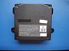
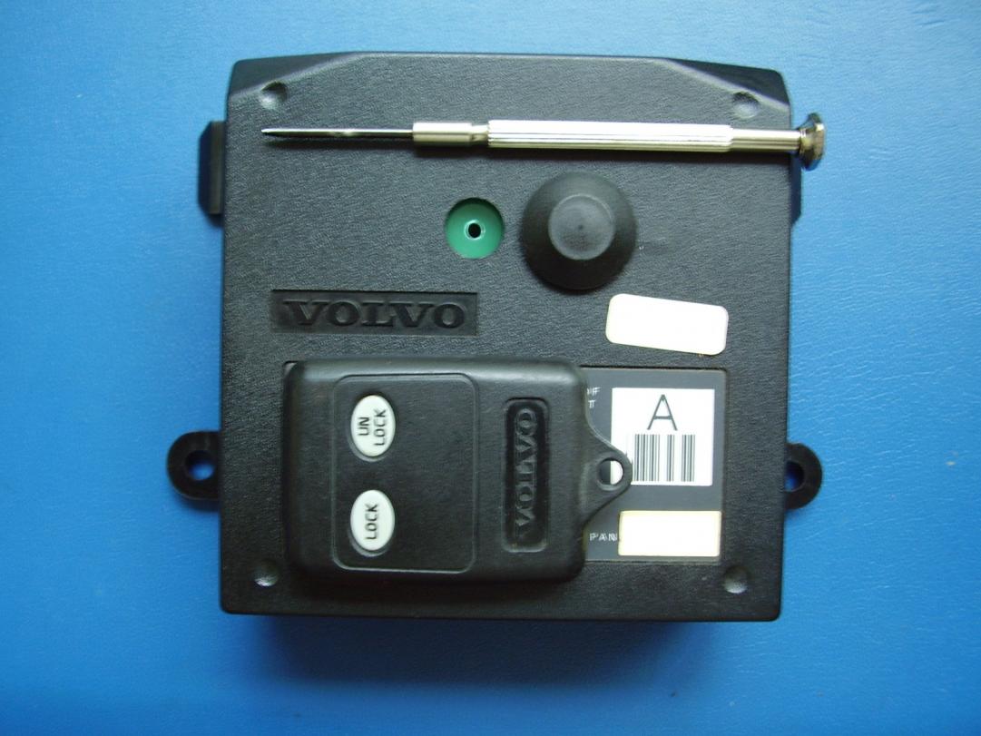
So, when you've finally pulled the target 9148645 module (or similar) from your car, you'll be holding what you see in View_1.jpg:
Proceed from this juncture when you're hooked into a good, static-safe workstation (unless you're fond of Sybil-like damaged CMOS behavior); and have a decent iron & solder sucker at the ready.
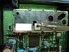
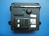
To start, we'll be removing the main cover. Simply loosen the four housing screws, and you're in (Initial_Disassembly.jpg):
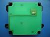
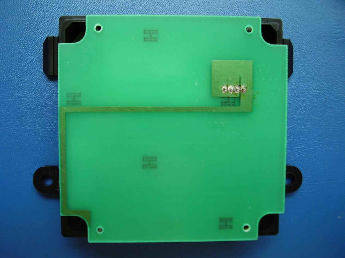
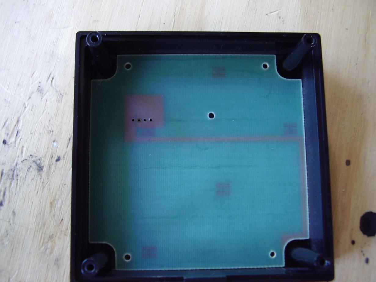
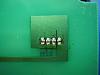
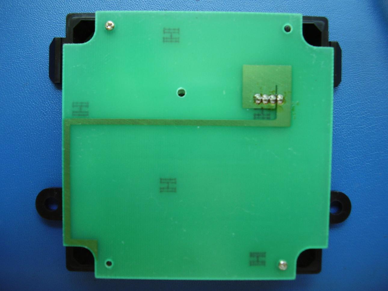
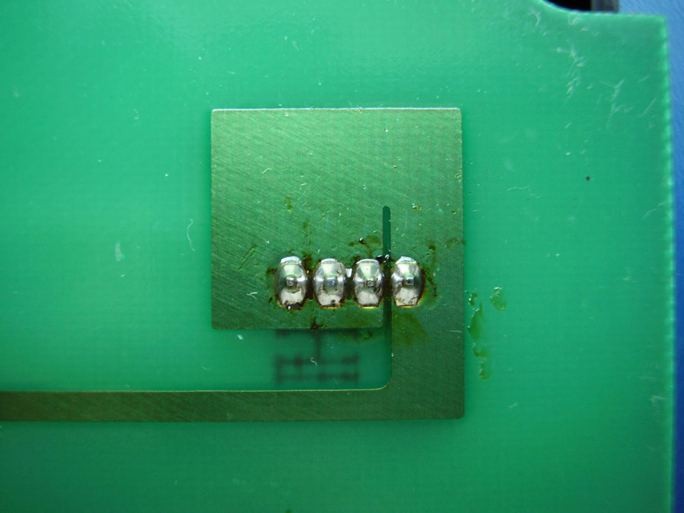
This presents the topside of the antenna board; a simple, one-trace affair which needs to be completely desoldered from its four-pin main board connector (upper righthand quadrant). Be thorough and neat; as the drillings are a close fit around the pins. After that's done, remove the two mounting screws (already out in the pic), and simply lift the board away. Receiver_View.jpg is what you'll see next:
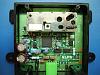
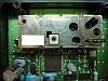
Zooming in, we can now locate the receiver module's variable inductor (Module_View.jpg):
Be thorough, as the ferrite material which the core is made from cannot withstand too much turning force without damage. While clearing, gently rotate the core back and forth a few times with a snug-fitting precision flatblade until about a half turn of reasonably free adjustment leeway is available. Be sure to return the core to its original orientation when you're done!
(continue with next post)
The following assumes you already have a good battery in the keyfob, and involves locating and removing the receiver/controller assembly; as subdetailed here (kick panel or "knee bolster" release) and here (actual module location). I've furnished a series of pics to follow along with for clarity; and, due to the forum's 5 count limitation on attached images, this all will span 3 posts in the end.
NOTE: What follows worked for me and my '95. I can't vouch for what might happen in any other particular case; nor, sadly, can I comment on whether or not the governing authorities in your area would consider the final result of these procedures as being “legal.”
Proceed with common sense, and at your own risk.
Still here? Good. Let's begin
So, when you've finally pulled the target 9148645 module (or similar) from your car, you'll be holding what you see in View_1.jpg:

Proceed from this juncture when you're hooked into a good, static-safe workstation (unless you're fond of Sybil-like damaged CMOS behavior); and have a decent iron & solder sucker at the ready.
To start, we'll be removing the main cover. Simply loosen the four housing screws, and you're in (Initial_Disassembly.jpg):
This presents the topside of the antenna board; a simple, one-trace affair which needs to be completely desoldered from its four-pin main board connector (upper righthand quadrant). Be thorough and neat; as the drillings are a close fit around the pins. After that's done, remove the two mounting screws (already out in the pic), and simply lift the board away. Receiver_View.jpg is what you'll see next:
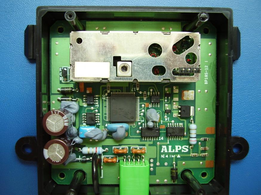
Zooming in, we can now locate the receiver module's variable inductor (Module_View.jpg):
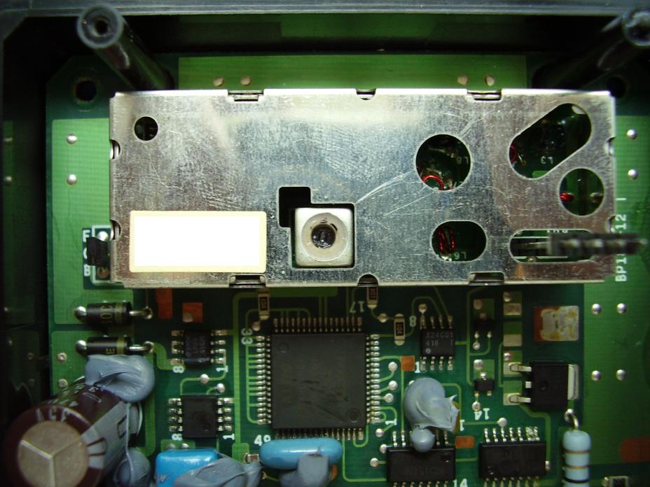
Final adjustment of this item when the module is reinstalled will be "key" to overcoming the range limitation which sets in as the assembly ages.
Next, take a small jeweler's screwdriver or pin and clear away all threadlocking adhesive from the core area (Cleanout.jpg):
Next, take a small jeweler's screwdriver or pin and clear away all threadlocking adhesive from the core area (Cleanout.jpg):
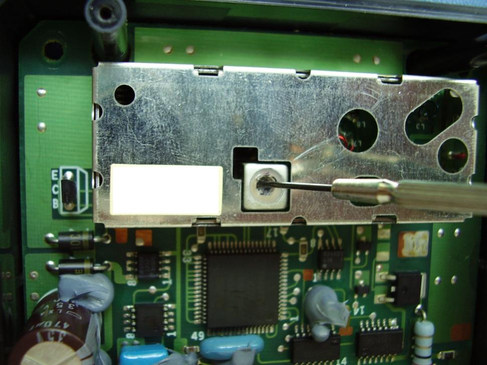
Be thorough, as the ferrite material which the core is made from cannot withstand too much turning force without damage. While clearing, gently rotate the core back and forth a few times with a snug-fitting precision flatblade until about a half turn of reasonably free adjustment leeway is available. Be sure to return the core to its original orientation when you're done!
(continue with next post)
Last edited by Cubic_Curiosity; May 13, 2015 at 06:51 PM. Reason: Clarity and Updates . . .
Thread Starter
|
Senior Member
Joined: Feb 2015
Posts: 120
Likes: 1
Procedure, continued:
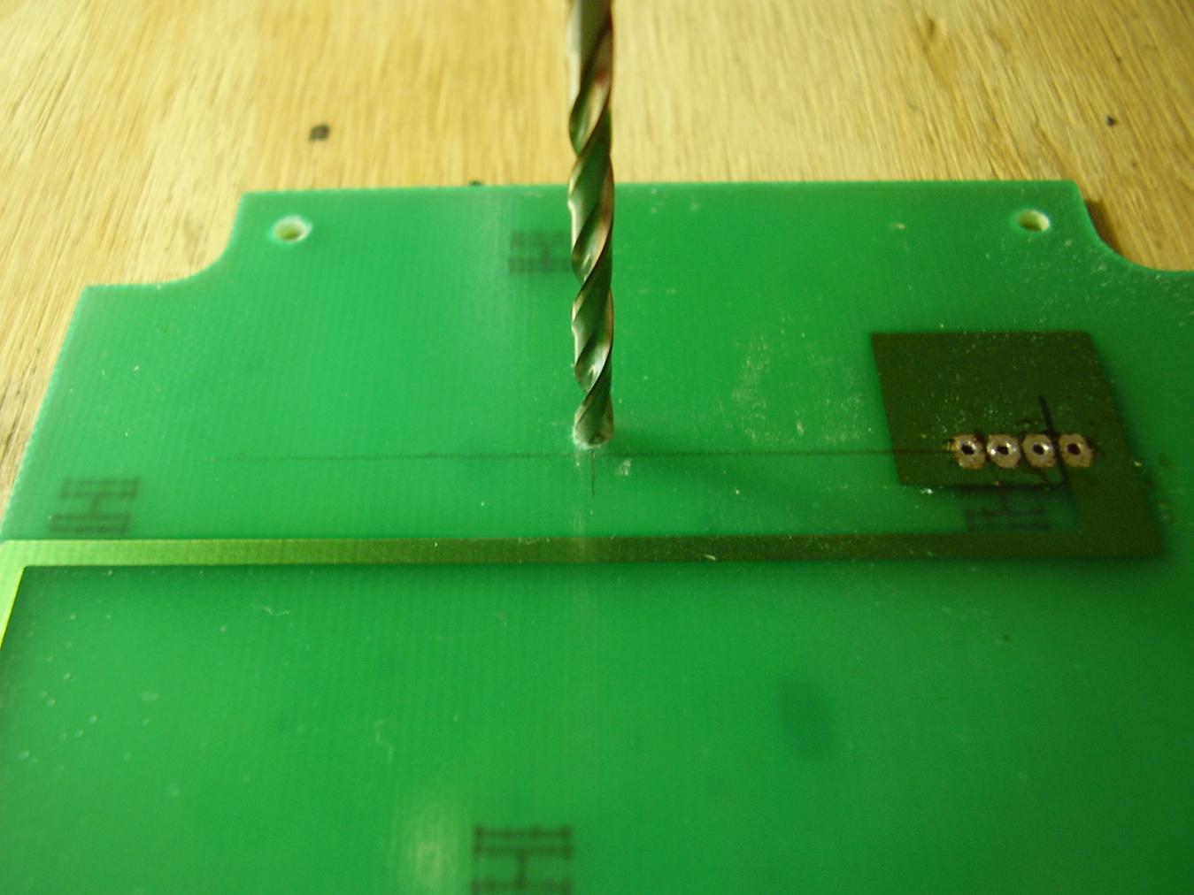
Next, we'll be drilling the required adjustment hole through the antenna board. I put together a nice series of images which detailed the layout work; but, due to old-camera issues, all was blurred spare this one image (Pilot_Drilling.jpg):
Note the alignment marks drawn on the board.
Thousand words:
Using a small square, draw a straight line taken through the centerline of the connector pin hole row toward the opposite board edge. Exactly one inch out from the edge of the last pin hole, intersect this line with another running perpendicularly up for half an inch or so. Set your drilling centerline exactly 1/16" up from this intersection, dimple punch (gently!) with a small nail, and drill your pilot hole. I use a small finger drill to get things started at this point, but do whatever works best for you and your setup. Work carefully and keep everything on center; and finish the hole with a 1/8" bit (I used a #36).
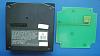
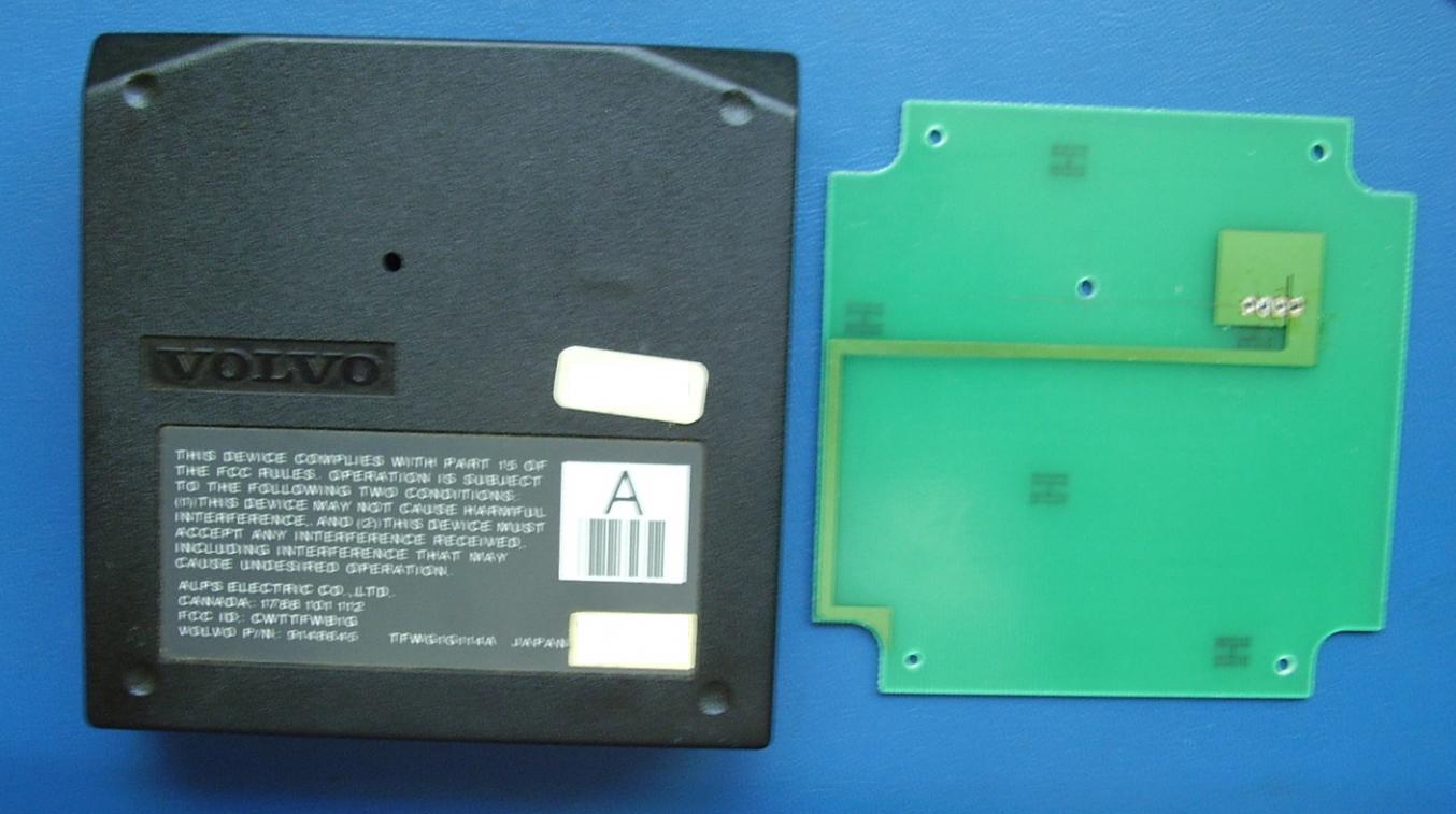
Next, set the drilled antenna board into the main cover while observing correct final assembly orientation. This will be a good, wiggle-free fit (Board_Orientation.jpg):

Using our new antenna board adjustment hole as a guide, simply drill a corresponding hole through the cover. All done, you'll wind up with this (SideXSide.jpg):
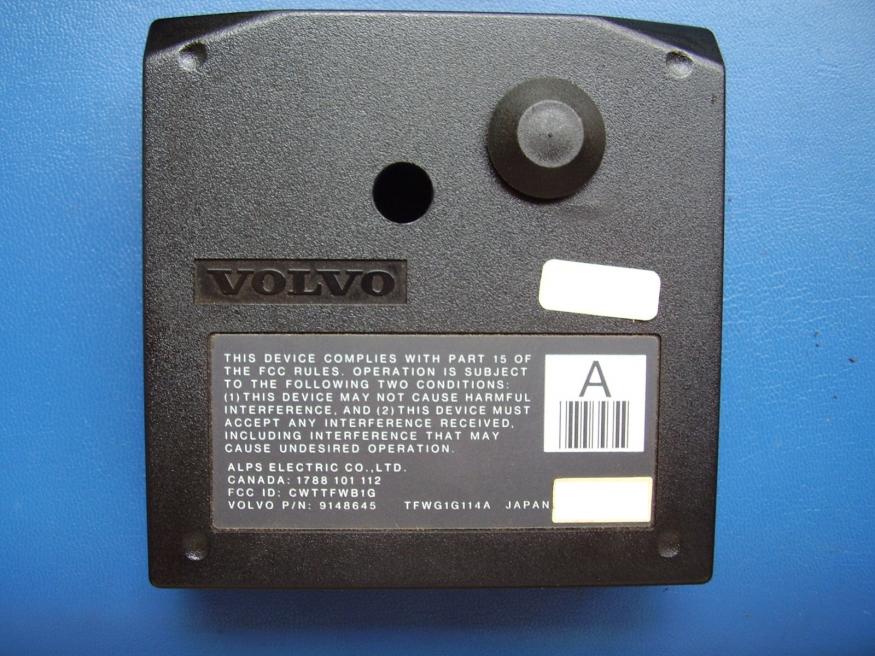
Next, enlarge the drilling in your cover to accommodate a small hole plug. I found a Hillman product at the local ACE hardware franchise which was nominally suitable for the work (#58181-A). Vastly overpriced at 23 cents, it wouldn't even fit the specified .375" hole; and, in the end, required a small cutout in the lip to allow insertion. Find something better if you can. For the record (Drilled_Cover.jpg):

(continue with next post)
Next, we'll be drilling the required adjustment hole through the antenna board. I put together a nice series of images which detailed the layout work; but, due to old-camera issues, all was blurred spare this one image (Pilot_Drilling.jpg):
Note the alignment marks drawn on the board.
Thousand words:
Using a small square, draw a straight line taken through the centerline of the connector pin hole row toward the opposite board edge. Exactly one inch out from the edge of the last pin hole, intersect this line with another running perpendicularly up for half an inch or so. Set your drilling centerline exactly 1/16" up from this intersection, dimple punch (gently!) with a small nail, and drill your pilot hole. I use a small finger drill to get things started at this point, but do whatever works best for you and your setup. Work carefully and keep everything on center; and finish the hole with a 1/8" bit (I used a #36).
Next, set the drilled antenna board into the main cover while observing correct final assembly orientation. This will be a good, wiggle-free fit (Board_Orientation.jpg):
Using our new antenna board adjustment hole as a guide, simply drill a corresponding hole through the cover. All done, you'll wind up with this (SideXSide.jpg):
Next, enlarge the drilling in your cover to accommodate a small hole plug. I found a Hillman product at the local ACE hardware franchise which was nominally suitable for the work (#58181-A). Vastly overpriced at 23 cents, it wouldn't even fit the specified .375" hole; and, in the end, required a small cutout in the lip to allow insertion. Find something better if you can. For the record (Drilled_Cover.jpg):
(continue with next post)
Last edited by Cubic_Curiosity; May 11, 2015 at 09:19 AM. Reason: Clarity and Updates . . .
Thread Starter
|
Senior Member
Joined: Feb 2015
Posts: 120
Likes: 1
Procedure, continued:
Time to begin reassembly.
Replace the antenna board, screw it down, and resolder the connector pins with standard lead-based solder (DON'T use lead-free; as the resulting "Frankenalloy" won't play nice over time).
(Board_Remount.jpg):
(SJ_View.jpg):
Replace the cover and housing screws, and all's done (Finished_Assy.jpg):
At this point, we'll take our modified module back to the car and reconnect it. Assume the position...
While pressing your flesh against the bare steel steering column (keep grounded during all of this!) and admiring the footpedals with one eye, enlist the services of a non-sadistic helper to operate the keyfob and check range along with you. Incrementally turn the inductor core clockwise; repeatedly stopping, removing the screwdriver, and grunting out "clunk checks" to your helper.
After about five agonizing minutes of this, you'll probably arrive at a final core adjustment of about 1/8 turn clockwise from origin; rewarding all with the full-spec 5 yards of RF convenience. Pop the hole plug in, place the unit back into its cradle, and, while losing as little hair as possible, hump your way back into the land of the vertical.
Then reinstall the knee bolster, dismiss the helper, and grab a soda.
Congratulations. You've just saved $300; and now have an assembly which will be serviceable over the next two decades
Cheers!
Last edited by Cubic_Curiosity; May 11, 2015 at 09:25 AM. Reason: Clarity and Updates . . .

Senior Member
Joined: Oct 2013
Posts: 260
Likes: 0
Cool write up. My car is later and has the "stribel" remote not the alps one.
The key to guaranteeing that you do not break the ferrite core is to use a plastic tool for adjustment. They were easily available in the olden days but now you have to get them from a specialty supplier. I think GC tools sells the set that I have.
The key to guaranteeing that you do not break the ferrite core is to use a plastic tool for adjustment. They were easily available in the olden days but now you have to get them from a specialty supplier. I think GC tools sells the set that I have.
Thread Starter
|
Senior Member
Joined: Feb 2015
Posts: 120
Likes: 1
@VDonkey:
Thanks for dropping by! On the basis of what doesn't exist helpwise, most out there seem to have either given up on this particular receiver or just buy an NOS replacement and toss the original out. Although operating range isn't all that great, and the system very basic, it would be a shame to simply dump the thing; as the unit gets the job done if it's working OK
I actually have one of those old alignment tools you mention. Unfortunately, in my instance at least, the tool just couldn't take the turning force needed for this particular core without simply oozing out of the slot; even after the retaining material was cleared. They must've used a ceramic tool at the factory for the work...
I guess there's a blessing in that level of baseline adjustment torque, as the core's probably not going to loosen and drift (mechanically) anytime too soon. Still, I would've appreciated an internal hex core (a few millicents more expensive) to allow for a more positive engagement during the necessary tweaking ops
All in all, I'd like to think of this as just one more way of resisting the consumer tendency to simply dump something of value just because it needs a bit of basic attention. Once again, that's clearly not what was planned when the unit was originally designed; but I think stuff like this is worth the trouble anyhow.
Happy tweaking!
Last edited by Cubic_Curiosity; May 12, 2015 at 09:04 AM. Reason: Typo :)

Thread
Thread Starter
Forum
Replies
Last Post