
Valve Cover - How to compress & Reinstall?


Thread Starter
|
Senior Member
Joined: May 2005
Posts: 230
Likes: 0
From:
So i'm trying to figure out how i'm going to re-attach my valve cover to the head and was wondering what methods you guys have used that work well.
The Haynes manual says that you need to make a bracket to secure the cams to the valve cover side. Then that whole assembly is put onto the head, and a special tool needs to be made up that threads into the spark plug holes in cylinder 1 & 5. the tool is basically just a threaded rod w/ a bar on top of the valve cover and is used to compress the cover to the head.
Is there any way i can do this without making up these tools? I was thinking of trying to use some of those ratcheting tie down straps wrapped around the block and valve cover if that would work.
What's the reason for attaching cams to the top cover? Couldn't you just put the cams on the lower half of the head instead of the valve cover side (so no special holding brackets are needed).
Also...what's the trick for timing? I *think* i understand the haynes writeup...just wondering if there are any other good writeups out there, as the haynes didn't clearly explain how to position the crankshaft....only explained the cams. [/align]

Administrator
Joined: Sep 2004
Posts: 36,349
Likes: 46
From: Orlando, Florida
You need to position the cams very close to the timing cover marks.
You can install the cam cover and all screws. Then slowly tighten them down working all the way around the cam cover. This way you won't crack it.
We made a set of tools at work but you could take a piece of square channel and slice one side off. Then cut a groove on each side so it sits in the spot where the black cover sits. Then drill a hole in the center. Then take an old spark plug and break all the pourclin out and weld a threaded rod to it and you will be good to go.
Thread Starter
|
Senior Member
Joined: May 2005
Posts: 230
Likes: 0
From:
I made the tool today to lock in the slotted ends of the camshafts...it's not the best but i'm hopin it will work. I think one side may not be perfectly parallel, and could be off by a degree or 2... not sure if it makes a big difference...definitely want to re-check the timing somehow before starting it for the first time...
What would you reccomend to use to lube up the camshafts? Haynes manual says engine oil..but i was thinking assembly lube since it will probalby be antoher 3-4 weeks before i actually start the engine. Was thinking that the assembly lube would not drip away and would be a better choice, although i'm slightly concerned w/ it possibly plugging up the tiny oil channels as it is much thicker.
When the lifters are put back in do they need to be oriented in any way? I know to put them back in the same holes they came out of, but there is that small oil passage in the lifter. Was wondering if that needed to be pointed towards the oil passage in the head, or if it matters at all.
Administrator
Joined: Sep 2004
Posts: 36,349
Likes: 46
From: Orlando, Florida
Assembly lube will be fine. If you are worried about anything once all together remove the coil wire and crank it about 10 times then start it after that. You will be fine with assembly lube though.
No special way on the lifters either. The head is ported so the oil will always get into the lifters.
The timing will get rechecked when you put the belt on anyways so thats no biggie.
No special way on the lifters either. The head is ported so the oil will always get into the lifters.
The timing will get rechecked when you put the belt on anyways so thats no biggie.
Thread Starter
|
Senior Member
Joined: May 2005
Posts: 230
Likes: 0
From:
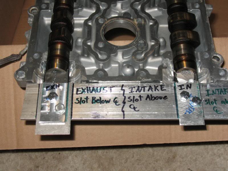
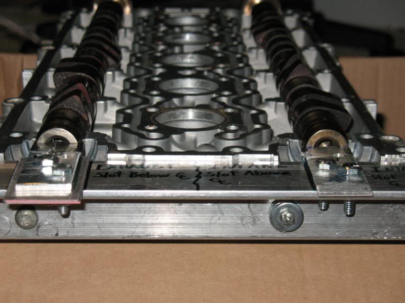
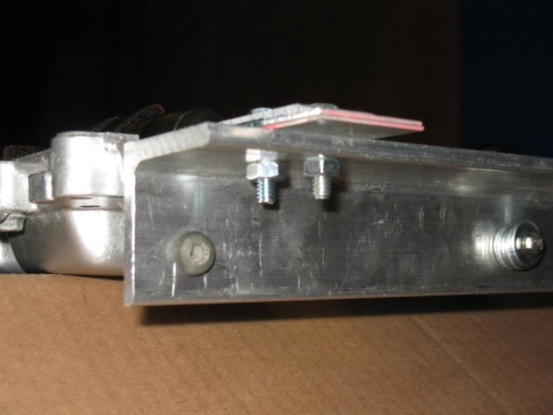
I made up a couple versions of a tool to hold the cam shafts...the first one didn't turn out too well, as my piece of angled aluminum wasn't perfectly parallel to the surface of the valve cover. Wanted it to be dead on, so on the 2nd version i slotted the holes to allow some adjustment...
Basically it's just a piece of aluminum that has slotted holes where you can use the screws from the camshaft position sensor, and one screw from the distributor cap w/ a bunch of washers so as not run that screw too far in. The CPS screw hole goes all the way through, so no worries of that, but a washer was needed on the other side between the tool and the valve cover...made it a bit more stable.
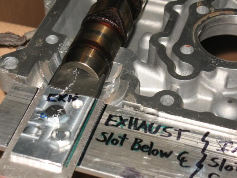
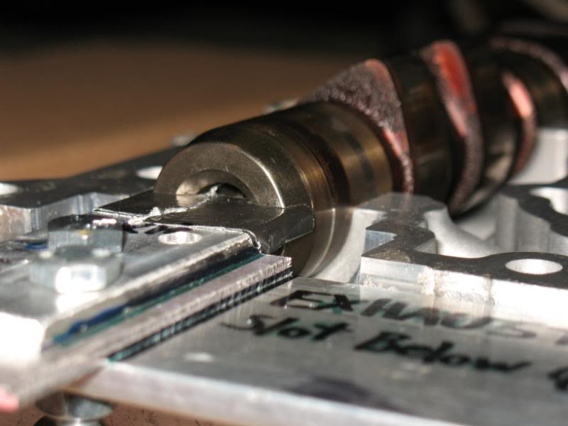
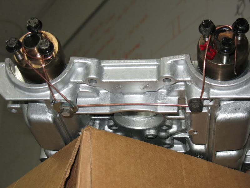
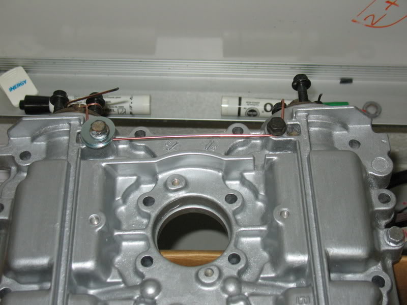
So the way it's supposed to be setup is there is a slot on the Rear end of the Camshafts (opposite end from timing gears). The slots are offset to be above or below the centerline. In the installed position, the slot on the intake cam should be above the centerline, and the slot on the exhaust cam is below the centerline.
There are 2 tabs that extend into these slots to lock them in place and prevent any rotation. The slots should be parallel to the bottom surface of the valve cover
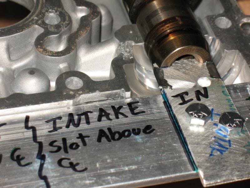
Used a washer on the Camshaft pos sensor side
Intake Side:
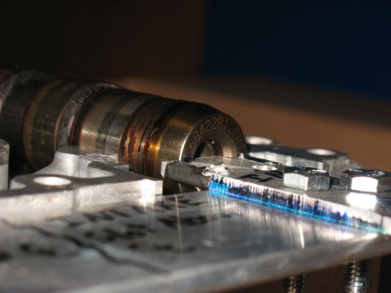
Exhaust side (locking tab is spaced up higher in this view)
I put the duct tape on there to get a nice snug fit...i milled a bit too much off on the locking tabs when i was making those so this helped get rid of any play/rotation of the cams.
Another view (intake on RH side)
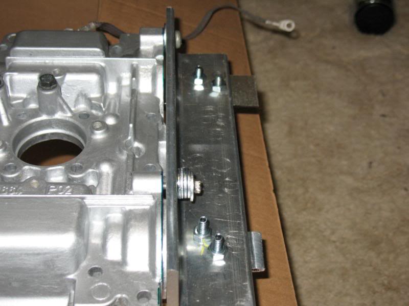
Screws for the Camshaft postion sensor (torx screw) and Dist Cap (w/ washers)
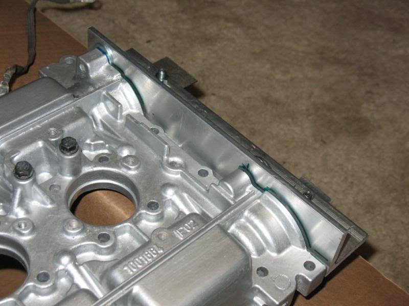
The front end is held in place w/ a piece of welding rod bent around the camshafts and held at the valve cover w/ the 2 screws. Nothing fancy, but if the rod is tight and there isn't any slack, it does a great job at holding these when the valve cover is upside down.
Basically it's just a piece of aluminum that has slotted holes where you can use the screws from the camshaft position sensor, and one screw from the distributor cap w/ a bunch of washers so as not run that screw too far in. The CPS screw hole goes all the way through, so no worries of that, but a washer was needed on the other side between the tool and the valve cover...made it a bit more stable.
So the way it's supposed to be setup is there is a slot on the Rear end of the Camshafts (opposite end from timing gears). The slots are offset to be above or below the centerline. In the installed position, the slot on the intake cam should be above the centerline, and the slot on the exhaust cam is below the centerline.
There are 2 tabs that extend into these slots to lock them in place and prevent any rotation. The slots should be parallel to the bottom surface of the valve cover
Used a washer on the Camshaft pos sensor side
Intake Side:
Exhaust side (locking tab is spaced up higher in this view)
I put the duct tape on there to get a nice snug fit...i milled a bit too much off on the locking tabs when i was making those so this helped get rid of any play/rotation of the cams.
Another view (intake on RH side)
Screws for the Camshaft postion sensor (torx screw) and Dist Cap (w/ washers)
The front end is held in place w/ a piece of welding rod bent around the camshafts and held at the valve cover w/ the 2 screws. Nothing fancy, but if the rod is tight and there isn't any slack, it does a great job at holding these when the valve cover is upside down.


Senior Member
Joined: Feb 2006
Posts: 821
Likes: 1
ORIGINAL: JPN
Some people are just so talented that it makes me amazed sometimes.
Some people are just so talented that it makes me amazed sometimes.
Now that´s talent! Getting more computational power from a €4000 machine than from a €3.5 million supercomputer. That´s revolutionary for medical tomography for poor countries like mine.
End of off topic. Sorry.

Senior Member
Joined: Apr 2007
Posts: 222
Likes: 0
From: Land of Excess and wasted Excess
ORIGINAL: axelmThis is totally off-topic, but when I read JPN´s post about talent, I couldn´t help thinking of http://fastra.ua.ac.be/en/index.html

Thread
Thread Starter
Forum
Replies
Last Post
momsmechanic
Volvo 850
17
Jul 6, 2009 12:33 PM
Methose
Volvo V40
2
Apr 4, 2009 06:58 PM